Recycling heat transfer system

A technology of heat conduction oil and heat conduction furnace, which is applied in the field of heat conduction systems, and can solve problems such as energy waste and reduced work efficiency

Inactive Publication Date: 2015-03-04
云南华香源香料有限公司
View PDF4 Cites 3 Cited by
  • Summary
  • Abstract
  • Description
  • Claims
  • Application Information

AI Technical Summary

Problems solved by technology

[0002] Many current heat conduction devices are single-oriented heat conduct

Method used


Image

  • Recycling heat transfer system
  • Recycling heat transfer system

Examples


Embodiment Construction

[0027] The present invention provides many applicable inventive concepts that can be embodied in numerous specific contexts. The specific examples described in the following embodiments of the present invention are only used as illustrations of specific embodiments of the present invention, and are not intended to limit the scope of the present invention.

[0028] The present invention will be further described below in conjunction with the accompanying drawings and specific embodiments.

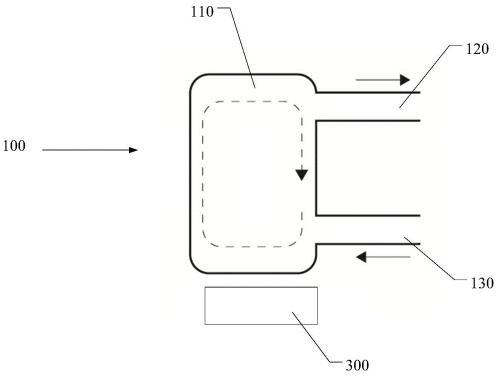
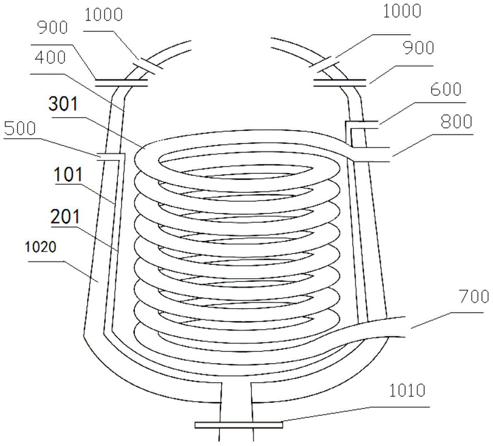
[0029] according to figure 1 and figure 2 As shown, among them: heat conduction furnace 100, heat conduction oil storage unit 110, heat outlet oil pipe 120, inlet cold oil pipe 130, heat conduction oil use device 200, first jacket layer 101, second jacket layer 201, coil pipe 301, Fractionation still body 400, oil inlet 500, oil outlet 600, heat transfer oil inlet 700, heat transfer oil outlet 800, feed inlet 900, sight glass 1000, valve 1010, insulation layer 1020, heating device 300. A...


PUM

PropertyMeasurementUnit
Thicknessaaaaaaaaaa

Abstract

The invention discloses a recycling heat transfer system comprising a heat-transfer oil furnace and a heat-transfer oil utilization device. The heat heat-transfer oil furnace comprises a heat-transfer oil containing unit, a hot oil outlet pipe and a cold oil inlet pipe. The hot oil outlet pipe and the cold oil inlet pipe are connected with the heat-transfer oil containing unit. The heat-transfer oil utilization device comprises a fractionation still body, a first jacket layer, a second jacket layer and a coil. The first jacket layer, the second jacket layer and the coil are arranged in the fractionation still body. A hollow chamber is formed in a place between the first jacket layer and the second jacket layer, with an oil inlet nozzle and an oil outlet nozzle provided in two ends thereof. The oil inlet nozzle and the oil outlet nozzle penetrate and are fixed onto the fractionation still body. A heat-transfer oil discharge outlet is arranged upon a heat-transfer oil feed inlet. Two ends of the coil are formed into a heat-transfer oil inlet nozzle and a heat-transfer oil outlet nozzle which penetrate the fractionation still body to be fixed onto the same. The heat-transfer oil outlet nozzle is arranged upon the heat-transfer oil inlet nozzle. The heat-transfer oil feed inlet and the heat-transfer oil inlet nozzle are connected with the hot oil outlet pipe. The heat-transfer oil discharge outlet and the heat-transfer oil outlet nozzle are connected with the cold oil inlet pipe. By the use of the recycling heat transfer system, efficiency is improved.

Description

technical field [0001] The invention relates to a heat conduction system, in particular to a recyclable heat conduction system. Background technique [0002] Many current heat conduction devices are single-direction heat conduction, which not only causes waste of energy, but also reduces work efficiency. [0003] Therefore, it is desirable to provide a recyclable heat conduction system that can save energy and improve work efficiency. Contents of the invention [0004] To this end, the present invention proposes a novel recyclable heat transfer system that can solve at least part of the above-mentioned problems. [0005] According to one aspect of the present invention, there is provided a recyclable heat conduction system, [0006] Including interconnected heat conduction furnace and heat conduction oil use device, [0007] The heat conduction furnace includes a heat conduction oil storage unit, and a heat outlet oil pipe and a cold oil inlet pipe connected to the heat...

Claims


Application Information

Patent Timeline
IPC IPC(8): F24H7/00
Inventor 张永忠张玉华张永杰
Owner 云南华香源香料有限公司
Why Eureka
Try Eureka