Device and method for detecting geometric errors of single-axis motions of machine tool

A technology of geometric error and detection equipment, which is applied in the direction of measuring devices, instruments, and optical devices, etc., can solve problems such as the inability to meet the processing accuracy of CNC machine tools, the inability of CNC machine tools to effectively identify geometric errors, and the identification accuracy not meeting the requirements.

Inactive Publication Date: 2015-03-04
GUANGDONG UNIV OF TECH
View PDF5 Cites 28 Cited by
  • Summary
  • Abstract
  • Description
  • Claims
  • Application Information

AI Technical Summary

Problems solved by technology

However, the nine-line method is affected by the placement error of the reflector of the laser interferometer. In some high-precision measurement occasions, the identification accuracy often fails to meet the requirements, resulting in the inability of the CNC machine tool to effectively identify and correct geometric errors, so it cannot meet the requirements. Requirements for machining accuracy of CNC machine tools

Method used


Image

  • Device and method for detecting geometric errors of single-axis motions of machine tool
  • Device and method for detecting geometric errors of single-axis motions of machine tool
  • Device and method for detecting geometric errors of single-axis motions of machine tool

Examples


Embodiment 1

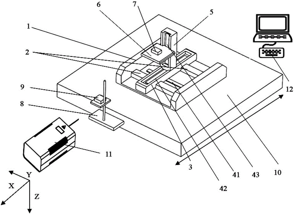
[0066] refer to Figure 1 ~ Figure 3 , a geometric error detection device for single-axis motion of a machine tool, including a processor 12, a laser interferometer 11, an interference mirror group 9, a mirror group 7, a bracket 8 for installing the interference mirror group 9, and a The fixed platform 1 on the single axis 10, the lower part of the fixed platform 1 is provided with a sliding guide rail 2 horizontally, and the sliding guide rail 2 is provided with a Y guide rail 3 which is perpendicular to the slide guide rail 2 and can slide along the slide guide rail 2, and on the Y guide rail 3 An X-guiding rail 5 that is perpendicular to the Y-guiding rail 3 and can slide along the Y-guiding rail 3 is provided, and a Z-directing sliding platform 6 that is perpendicular to the X-guiding rail 5 and can slide along the X-guiding rail 5 is provided on the X-guiding rail 5; And the mirror group 7 can move along the X-axis direction, the Y-axis direction and the Z-axis direction ...

Embodiment 2

[0074] The detection method of the detection device for the geometric error of the single-axis motion of the machine tool described in Embodiment 1 includes:

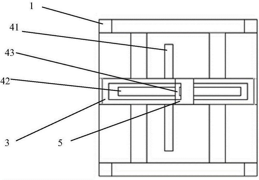
[0075] S1, refer to Figure 4 , taking the direction of the sliding guide rail 2 as the X axis, the direction of the X guide rail 5 as the Y axis, and the direction of the Y guide rail 3 as the Z axis, after the spatial coordinate system is established, the origin of the spatial coordinate system is selected, and the single axis of the machine tool is driven 10 moves along the X-axis direction; here, the origin of the space coordinate system is generally selected as the intersection of the sliding guide rail 2, the X-guiding rail 5 and the Y-guiding rail 3.

[0076] S2. By adjusting the Y guide rail 3 and the Z sliding platform 6, the reflector group 7 is located in three different positions, and at the same time, at each position, the machine tool is driven to move along the X axis so that the reflector group 7 moves l...


PUM


Abstract

The invention discloses a device and a method for detecting geometric errors of single-axis motions of a machine tool. The detection device comprises a processor, a laser interferometer, an interference mirror unit, a bracket and a fixed platform; a sliding rail is horizontally arranged at the lower part of the fixed platform; a Y-direction rail vertical to the sliding rail and capable of sliding along the sliding rail is arranged on the sliding rail; an X-direction rail vertical to the Y-direction rail and capable of sliding along the Y-direction rail is arranged on the Y-direction rail; a Z-direction rail vertical to the X-direction rail and capable of sliding along the X-direction rail is arranged on the X-direction rail; a first grating ruler arranged on the fixed platform, a second grating ruler arranged on the X-direction rail and a third grating ruler arranged on the Y-direction rail are connected with the processor; and a reflection mirror unit is installed on a Z-direction sliding platform. The device and the method for detecting geometric errors of the single-axis motions of the machine tool have high measuring accuracy and high measuring speed and can be widely applied to the detection field of geometric errors of the single-axis motions of the machine tool.

Description

technical field [0001] The invention relates to the detection field of the geometric error of the single-axis motion of a machine tool, in particular to a detection device and a detection method for the geometric error of the single-axis motion of the machine tool. Background technique [0002] As the aerospace, military, shipbuilding, automobile and other industries have higher and higher requirements for precision parts processing, the precision performance of machine tools is more important, and the research on improving the precision of CNC machine tools has attracted much attention. Dimensional accuracy is the most important factor to determine the machining accuracy of CNC machine tools, and the geometric accuracy of CNC machine tools is the direct cause of affecting dimensional accuracy. The measurement of the geometric error of the single-axis movement of the machine tool is the basic link to improve the geometric accuracy of the machine tool. How to accurately measu...

Claims


Application Information

Patent Timeline
Patent Type & Authority Applications(China)
IPC IPC(8): G01B11/00
Inventor 彭伟超王素娟陈新度夏鸿建欧阳祥波王晗李克天刘强
Owner GUANGDONG UNIV OF TECH
Why Eureka
Try Eureka