
Probe and testing device

A probe and electrical testing technology, applied in the field of probes and test equipment, can solve the problems of poor test signal, unstable pin body 1, inaccurate test, etc., to improve test efficiency and test accuracy, and to adjust easily Fast, accurate results

Active Publication Date: 2015-03-04
BOE TECH GRP CO LTD
View PDF9 Cites 7 Cited by
  • Summary
  • Abstract
  • Description
  • Claims
  • Application Information

AI Technical Summary

Problems solved by technology

In the process of introducing the test signal in the signal line 2 into the test position by the probe, it is usually necessary to pierce the exposed end of the needle body 1 into the test position, thus making the needle body 1 easy to insert during multiple insertions. Friction occurs between the needle body and the metal core, which leads to loose connection between the needle body 1 and the metal core after being inserted many times, so that the needle body 1 is prone to be unstable and the needle runs when it is inserted into the test position, and then Leading to poor test signal introduction and inaccurate testing; at the same time, the needle body 1 is unstable or the needle runs out, which will seriously affect the test efficiency

Method used


Image

  • Probe and testing device
  • Probe and testing device
  • Probe and testing device

Examples


Embodiment 1

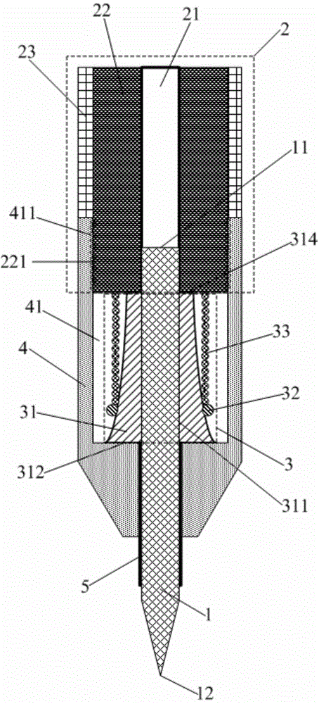
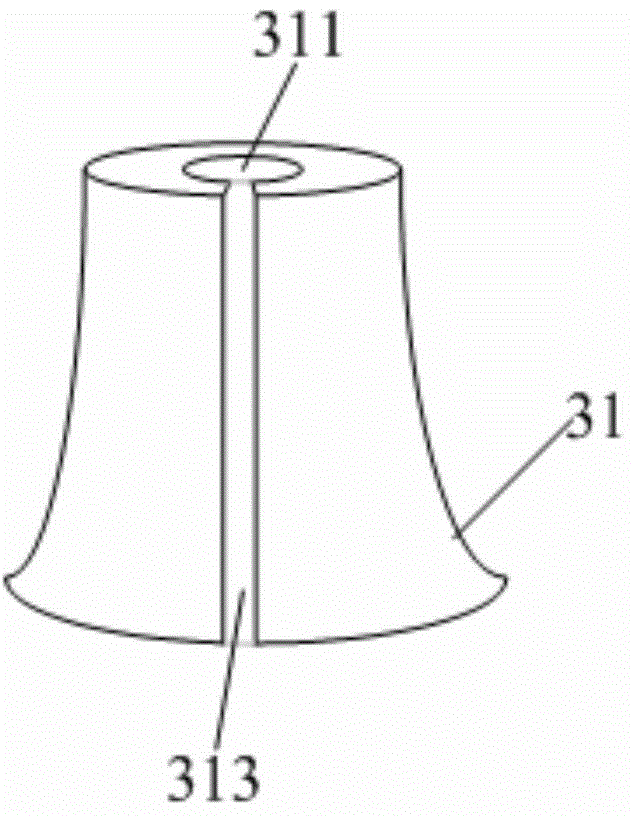
[0030] This embodiment provides a probe for electrical testing, such as Figure 2-5 As shown, it includes a needle body 1 and a signal wire 2. The signal wire 2 includes a wire core 21 and an insulating layer 22 wrapped around the wire core 21. The first end 11 of the needle body 1 is connected to the wire core 21, and the second end of the needle body 1 The end 12 is exposed for testing and also includes a clamping structure 3 for clamping the needle body 1 .

[0031] The setting of the clamping structure 3 can make the needle body 1 be firmly clamped, so that the needle body 1 is not easy to be unstable or run away during the test process, ensuring that the test signal can be introduced normally, thereby not only ensuring the signal test Accuracy, but also improve the efficiency of signal testing.

[0032] In this embodiment, the wire core 21 is a conductive hollow tube wrapped inside the insulating layer 22 , and the inner diameter of the hollow tube is equal to the diamet...

Embodiment 2

[0043] This embodiment provides a probe for electrical testing. The difference from Embodiment 1 is that the clamping structure in this embodiment only includes a cone and does not include a pressure ring and a spring. Wherein the structure of the frustum is the same as in Example 1.

[0044] Since the cone is made of rubber or plastic material and has a certain degree of elasticity, it can keep the needle body clamped so that the needle body is not easy to be unstable or run out of the needle.

[0045] Other structures and materials of the probe in this embodiment are the same as those in Embodiment 1, and will not be repeated here.

[0046] Beneficial effects of embodiment 1-2: the probe in embodiment 1-2, by setting the clamping structure, the needle body can be firmly clamped, so that the needle body is not easy to be unstable or run out during the test phenomenon, to ensure that the test signal can be introduced normally, thereby not only ensuring the accuracy of the sig...

Embodiment 3

[0048] This embodiment provides a testing device, including the probe in any one of Embodiments 1-2.

[0049] By using the probe in any one of the embodiments 1-2, the testing efficiency and testing accuracy of the testing equipment are improved.


PUM


Abstract

The invention provides a probe and a testing device. The probe comprises a probe body and a signal wire. The signal wire comprises a wire core and an insulation layer wrapping the periphery of the wire core. The first end of the probe body is connected with the wire core, and the second end of the probe body is exposed for testing. The probe further comprises a clamping structure for clamping the probe body. By means of the clamping structure, the probe body can be firmly clamped, so that the problem that the probe body cannot stab stably or is easy to pull out in the testing process is solved, the testing signals can be led in normally, signal testing accuracy is ensured, and signal testing efficiency is further improved. Meanwhile, the probe body is convenient and quick to adjust by means of the clamping structure.

Description

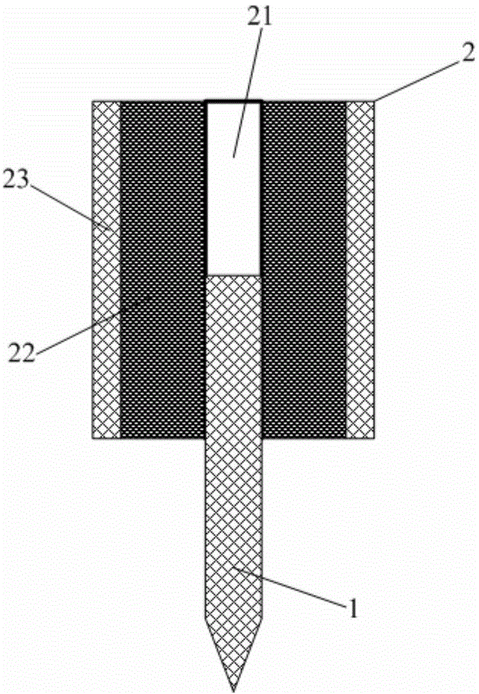
technical field [0001] The invention relates to the technical field of semiconductor electrical testing, in particular to a probe and testing equipment. Background technique [0002] In the process of testing the electrical properties of semiconductors and the electrical properties of TFT LCD Array substrates (TFT LCD Array), it is often necessary to use a probe device to connect terminals of the testing instrument. [0003] Such as figure 1 As shown, the probe generally consists of a needle body 1 and a signal line 2 . The signal line 2 includes three parts: the outermost metal shielding layer 23 , the middle insulating layer 22 , and the innermost metal core, namely the wire core 21 . One end of the needle body 1 is connected to the innermost metal core of the signal line 2, and the other end of the needle body 1 is exposed for introducing the test signal of the signal line 2 to the test position. [0004] The metal shielding layer 23 wraps the entire signal line 2 to e...

Claims


Application Information

Patent Timeline
Patent Type & Authority Applications(China)
IPC IPC(8): G01R31/26G01R1/067G01R1/04
Inventor 孙俊民薛金祥王小虎
Owner BOE TECH GRP CO LTD
Learn More