Axial-radial magnetic field electromagnetic planetary gear power divider

A technology of power splitter and planetary gear, which is applied in magnetic circuits, electrical components, electromechanical devices, etc., can solve the problems of incapable power output, complex structure, and bulky volume, and achieve the effects of reducing exhaust emissions, small volume, and low cost

Active Publication Date: 2015-03-04
HARBIN INST OF TECH
View PDF8 Cites 4 Cited by
  • Summary
  • Abstract
  • Description
  • Claims
  • Application Information

AI Technical Summary

Problems solved by technology

[0005] The purpose of the present invention is to solve the problem that the engine and other components of the system in the existing series, parallel and hybrid drive devices cannot be coordinated simply and efficiently, so that the whole system has bulky volume, complex structure, high cost, and limited performance. To solve the problem of not being able to efficiently output power, an axial-axial radial magnetic field electromagnetic planetary gear power divider is provided

Method used


Image

  • Axial-radial magnetic field electromagnetic planetary gear power divider
  • Axial-radial magnetic field electromagnetic planetary gear power divider
  • Axial-radial magnetic field electromagnetic planetary gear power divider

Examples


specific Embodiment approach 1

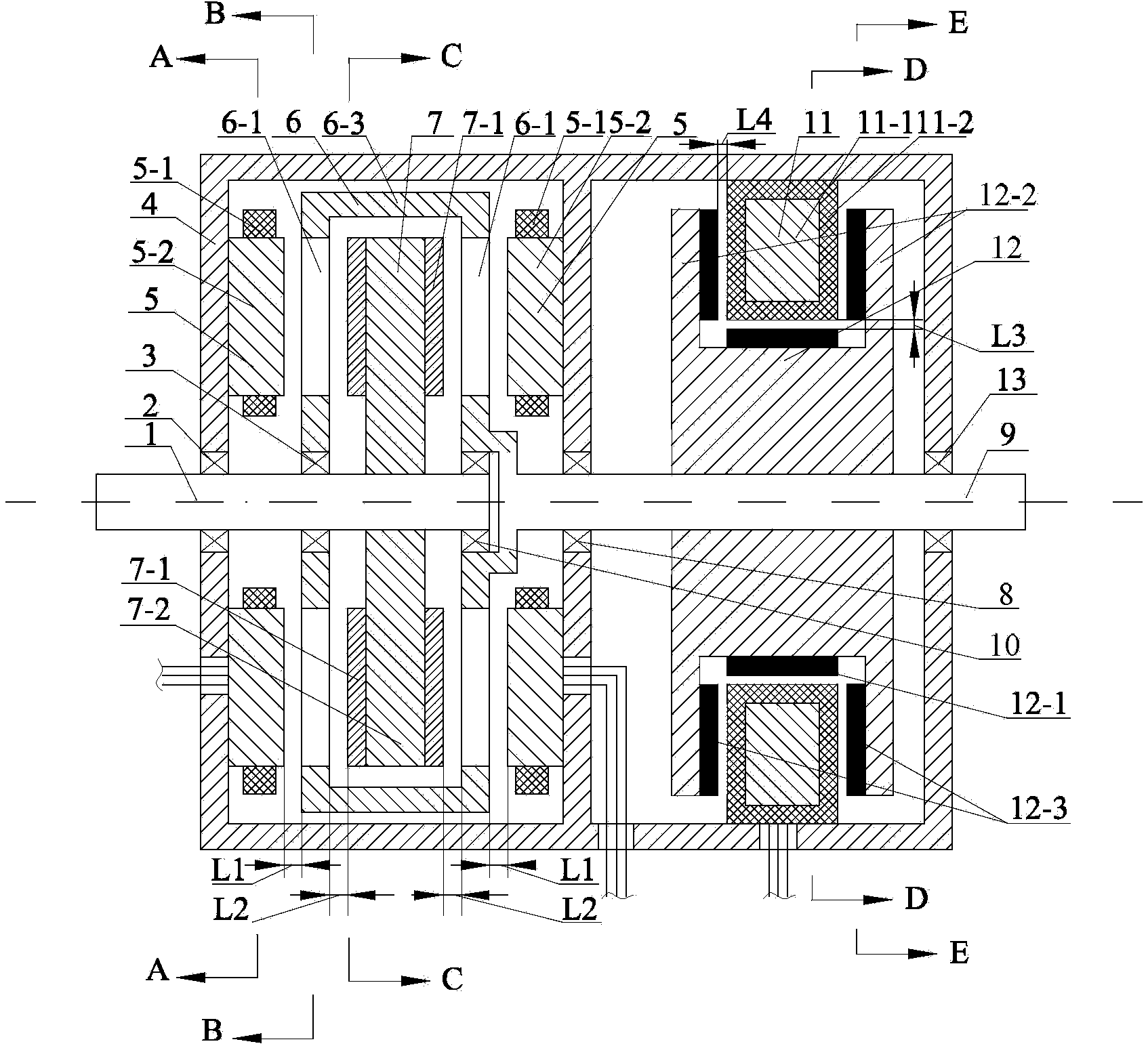
[0050] Specific implementation mode 1: the following combination Figure 1 to Figure 8 To explain this embodiment, in the axial-axis radial magnetic field electromagnetic planetary gear power distributor of this embodiment, the housing 4 is divided into left and right parts by a partition, the axial double rotor motor and the axial radial torque adjustment motor are respectively Set in the left and right parts of the housing 4, the axial double-rotor motor includes two first stators 5, a first permanent magnet rotor 6, a magnetizing rotor 7, a magnetizing rotor output shaft 1 and a permanent magnet rotor output Shaft 9, the axial radial torque adjustment motor includes a second stator 11 and a second permanent magnet rotor 12, and the permanent magnet rotor output shaft 9 simultaneously serves as the rotor shaft of the axial radial torque adjustment motor,

[0051] The second stator 11 of the axial radial torque adjustment motor is fixed on the inner circular surface of the right ...

specific Embodiment approach 2

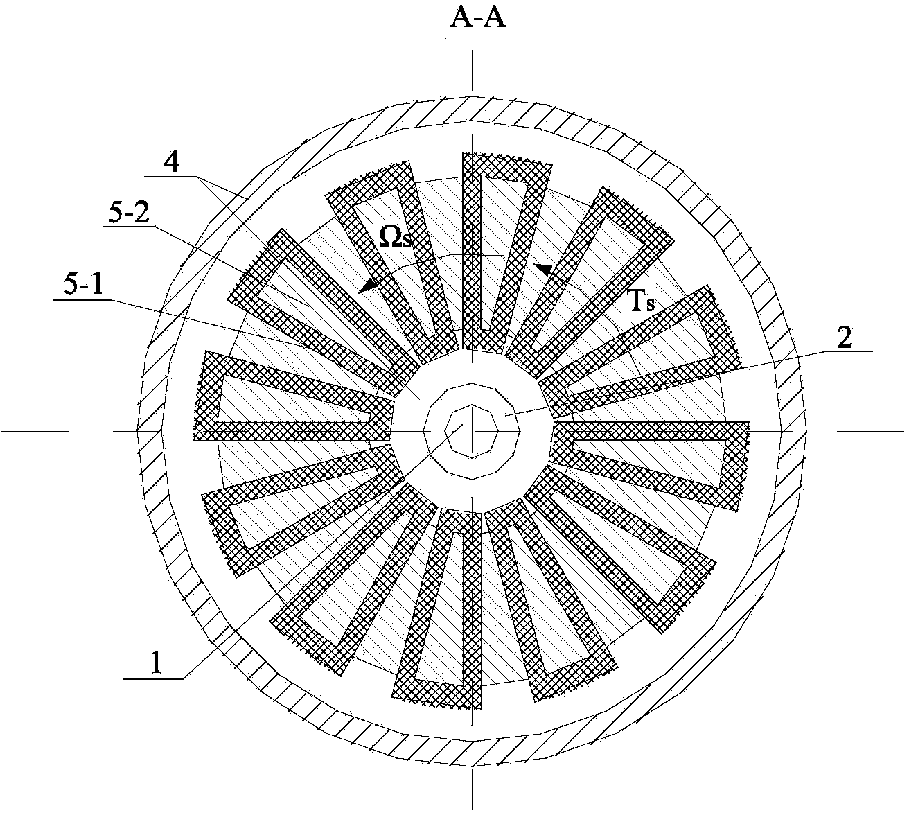
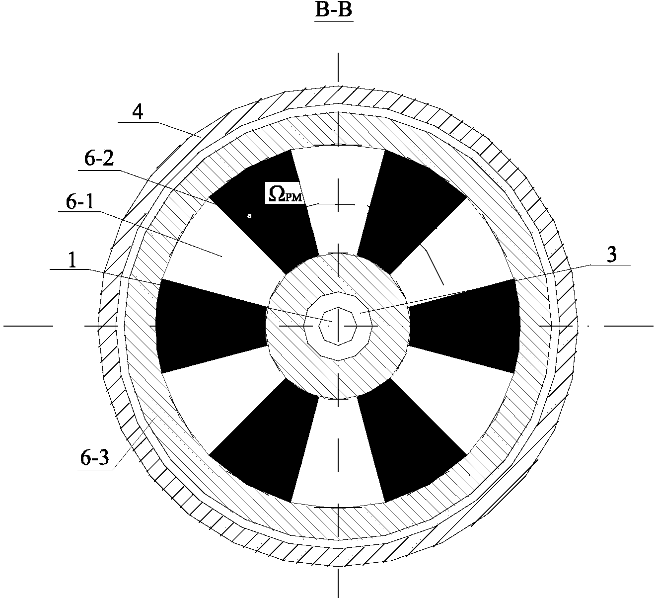
[0060] Specific implementation manner 2: the following combination Figure 1 to Figure 6 , Figure 15 to Figure 23 To illustrate this embodiment, this embodiment will further explain the first embodiment. The first permanent magnet rotor 6 includes a rotor support 6-3, 2n first permanent magnet units 6-1, and 2n second permanent magnet units 6-2. Both end surfaces of the rotor support 6-3 facing the two first stators 5 are provided with n first permanent magnet units 6-1 and n second permanent magnet units 6-2, and n first permanent magnet units 6 -1 and n second permanent magnet units 6-2 are alternately arranged along the circumferential direction, the magnetizing directions of n first permanent magnet units 6-1 are the same, and the magnetizing directions of n second permanent magnet units 6-2 are the same , The magnetizing directions of the first permanent magnet unit 6-1 and the second permanent magnet unit 6-2 are opposite; the magnetizing directions of the first permanent...

specific Embodiment approach 3

[0101] Specific implementation manner three: the following combination Figure 7 with Picture 8 To illustrate this embodiment, this embodiment will further explain the first embodiment. The first permanent magnet rotor 6 includes a rotor support 6-3, 2n first permanent magnet units 6-1, and 2n first permanent magnet rotor cores 6-4. , The two end faces of the rotor support 6-3 facing the two first stators 5 are provided with n first permanent magnet units 6-1 and n first permanent magnet rotor cores 6-4, n first permanent magnets The unit 6-1 and the n first permanent magnet rotor cores 6-4 are alternately arranged in the circumferential direction, and the magnetizing directions of the n first permanent magnet units 6-1 are the same.

[0102] The axial double-rotor motor of this embodiment saves half of the amount of permanent magnets under the permanent magnet field with the same number of pole pairs.


PUM


Abstract

An axial-radial magnetic field electromagnetic planetary gear power divider belongs to the field of automobile motors, and aims to solve the problem that in a conventional tandem-type / parallel-type / series-parallel driving device, the engine cannot simply and efficiently cooperate with other parts of a system, so that the system is large in size, complex in structure and restricted in performance and cannot output power effectively. The power divider is characterized in that a casing is divided into two parts which are provided with an axial double-rotor motor and an axial radial torque regulation motor; a magnetic flux regulating rotor with q protrusion units and in the axial double-rotor motor is driven by a primary machine, and a stator forms a 2p pole field, the required rotate speed is output by an output shaft of a p-m rotor with 2n poles, wherein, the relation expression that p equals to the absolute value of hn and kq is met, besides, the output rotate speed does not depend on the input rotate speed, so that infinitely variable speed can be realized; the torque regulation motor inputs driving torque or retarding torque according to the requirement of practical load to meet the requirement on practical torque of the load, so that the input energy and the output energy of the output shaft of the p-m rotor are balanced.

Description

Technical field [0001] The invention relates to a composite structure motor, belonging to the field of motors. Background technique [0002] The fuel consumption and exhaust pollution of traditional internal combustion engine vehicles are hot issues of worldwide concern. The use of electric vehicles can achieve low energy consumption and low emissions. However, due to the energy density, lifespan, and price of the battery, which is one of the key components of electric vehicles, the cost-effectiveness of electric vehicles cannot compete with traditional internal combustion engine vehicles. In this case, hybrid electric vehicles that integrate the advantages of internal combustion engine vehicles and electric vehicles have developed rapidly and have become a hot spot in the development of new vehicles. [0003] The characteristics of the existing tandem drive device are: the engine is not affected by the driving conditions of the car, and it always runs stably in its best working a...

Claims


Application Information

Patent Timeline
IPC IPC(8): H02K16/00
CPCH02K51/00H02K2201/03
Inventor 佟诚德白金刚周承豫宋志翌王伟男
Owner HARBIN INST OF TECH
Why Eureka
Try Eureka