Power output equipment, hydraulic stirrer, high-pressure reaction kettle including power output equipment and hydraulic stirrer, and system

A high-pressure reactor and power output technology, which is applied to mixers with rotating stirring devices, mechanical equipment, mixer accessories, etc., can solve problems such as shortened service life, accelerated bearings, and corrosion of equipment to achieve safe, economical, and efficient operation. The effect of long equipment life

Pending Publication Date: 2019-03-22
杨卫东
View PDF8 Cites 1 Cited by
  • Summary
  • Abstract
  • Description
  • Claims
  • Application Information

AI Technical Summary

Problems solved by technology

However, this sealing method still does not achieve the purpose of isolating the atmosphere in the sealed cover from the reactor, which makes the gas reactants in the reactor possibly enter the sealed cover and corrode the equipment therein
This is especially true in the case of high-pressure reactors. Since the pressure of the reactor can be transmitted to the sealed cover through the support bearing, as the pressure of the reactor rises, the raw material gas, mixed steam, and raw material dust in the reactor will flow up to the In the sealing cover, if there is corrosive gas, it will cause corrosion to the components in the sealing cover. Since there is no cooling measure, the heat of reaction will be transmitted to the bearing through the stirring shaft and steam to accelerate the damage of the bearing. Excessive temperature will also make the hydraulic motor The premature aging of the rubber sealing element shortens the service life; the stirring shaft shown in the attached drawing of the patent has no lower support, and the swing of the stirring shaft is borne by a bearing on the support, which will accelerate the damage of the bearing
Therefore, this equipment is not suitable for high-pressure reactors

Method used


Image

  • Power output equipment, hydraulic stirrer, high-pressure reaction kettle including power output equipment and hydraulic stirrer, and system
  • Power output equipment, hydraulic stirrer, high-pressure reaction kettle including power output equipment and hydraulic stirrer, and system
  • Power output equipment, hydraulic stirrer, high-pressure reaction kettle including power output equipment and hydraulic stirrer, and system

Examples


Embodiment 1

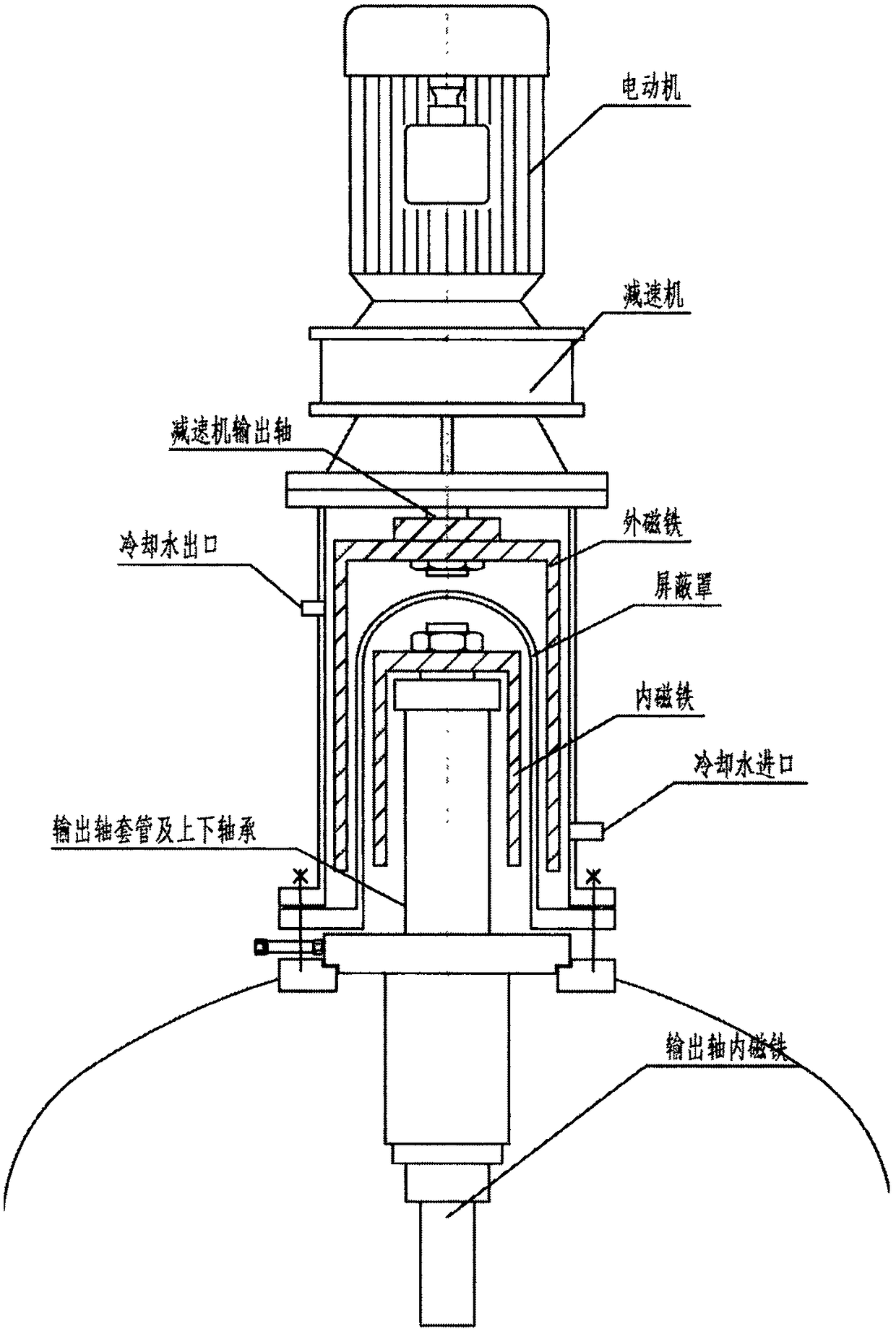
[0061] figure 2is a schematic diagram of one embodiment of a stirrer according to the present application. Wherein, the agitator includes a power output device according to the present application, and the power output device includes a hydraulic motor (3), and the hydraulic motor has a motor coupling (6), a power output shaft (7) and a hydraulic oil pipe (4, 5), the motor coupling (6) is connected to one end of the power output shaft (7), and the power of the hydraulic motor (3) is transmitted to the power through the motor coupling (6) Output shaft (7); shielding case (24), described shielding case (24) has an open end, and described open end is equipped with support sleeve (10), and described hydraulic motor (3) is accommodated in described shielding case ( 24), the other end of the power output shaft (7) passes through the support sleeve (10) for power output, and the hydraulic oil pipes (4, 5) pass through the shield cover (24) , used to connect the hydraulic station (...

Embodiment 2

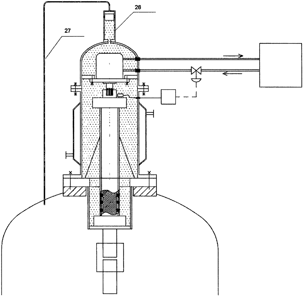
[0066] image 3 is a schematic diagram of one embodiment of a stirrer according to the present application. its structure and figure 2 The difference is that a piston (26) and a connecting pipe (27) are arranged on the shielding cover, and one end of the piston (26) communicates with the inside of the shielding cover (24), and the piston (26 ) is connected to the communication pipe (27), and the communication pipe (27) communicates with the inside of the high pressure reactor. Such design can make the incompressible fluid (being hydraulic oil 23) in the shielding cover keep balance when subjected to upper pressure and lower pressure, and the pressure in the hydraulic oil (23) is the pressure of the reactor, or in other words and the pressure of the reactor. The pressure is very close.

Embodiment 3

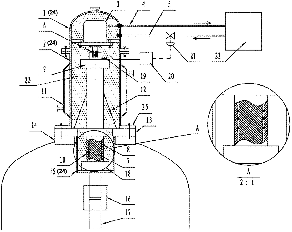
[0070] Figure 4 It is another embodiment of the present application, which is similar to the technical solution of Embodiment 1, except that the sealing connection between the support plate and the upper and lower cylinders of the shield adopts a different design. In the present application, the specific design of the support plate is not limited, as long as the upper and lower sealing surfaces of the support plate can achieve a good sealing effect.


PUM


Abstract

The invention provides power output equipment. The power output equipment comprises a hydraulic motor (3), a shielding cover (24), a sealing element (8) and an incompressible fluid (23), wherein the hydraulic motor is provided with a motor coupler (6), a power output shaft (7) and hydraulic oil pipes (4, 5); a support sleeve (10) is arranged at an open end of the shielding cover (24); the hydraulic motor (3) is accommodated in the shielding cover (24); the other end of the power output shaft (7) passes through the support sleeve (10); the sealing oil pipes (4 and 5) pass through the shieldingcover (24), and are sued for connecting a hydraulic station (22); the sealing element (8) is arranged between the support sleeve (10) and the power output shaft (7), so that an area, in which the hydraulic motor is accommodated, in the shielding cover (24) forms an enclosed space; the incompressible fluid (23) is located in the enclosed space; the enclosed space is fully filled with the incompressible fluid. The equipment provided by the invention is particularly suitable for high-pressure reaction kettles.

Description

technical field [0001] The application belongs to the field of mechanical equipment, and in particular relates to a power output device, a hydraulic agitator, a high-pressure reactor containing the same, and a reactor system including the hydraulic agitator. Background technique [0002] At present, in the high-pressure reactor or the reactor of special medium used in the laboratory and industrial production, in order to ensure the airtightness, a magnetic coupling-driven stirrer (magnetic stirrer) is used, (such as figure 1 As shown in ) the agitator is driven by a drive motor through a reducer to drive a hollow cylindrical outer magnet to rotate, and the inner magnet is driven to rotate by magnetic force. The inner magnet is connected to the stirring shaft to make the stirring shaft rotate. The pressure shield is isolated to achieve static sealing of the stirring drive. The magnetic force line coupling between the power drive of the magnetic stirrer and the stirring shaft...

Claims


Application Information

Patent Timeline
Patent Type & Authority Applications(China)
IPC IPC(8): B01J3/04B01F15/00B01F7/16F15B11/08
CPCB01J3/04F15B11/08B01F27/80B01F35/2111B01F35/2213B01F35/221422B01F35/32045
Inventor 杨卫东
Owner 杨卫东
Why Eureka
Try Eureka