Wear adjustment device of a disc brake and corresponding disc brake

A technology of disc brakes and adjustment devices, applied in the direction of brake parts, brakes, brake types, etc., to achieve the effect of reducing the number of components, saving space, and saving installation space

Inactive Publication Date: 2015-03-04
KNORR-BREMSE SYST FUER NUTZFAHRZEUGE GMBH
View PDF8 Cites 15 Cited by
  • Summary
  • Abstract
  • Description
  • Claims
  • Application Information

AI Technical Summary

Problems solved by technology

The problem with existing systems is that they are based on frictional locking and therefore only work within a very narrow range or in dependence on temperature and vibrations, that is to say under the influence of temperature and vibrations Additional measures are required to stabilize the air gap

Method used


Image

  • Wear adjustment device of a disc brake and corresponding disc brake
  • Wear adjustment device of a disc brake and corresponding disc brake
  • Wear adjustment device of a disc brake and corresponding disc brake

Examples


Embodiment Construction

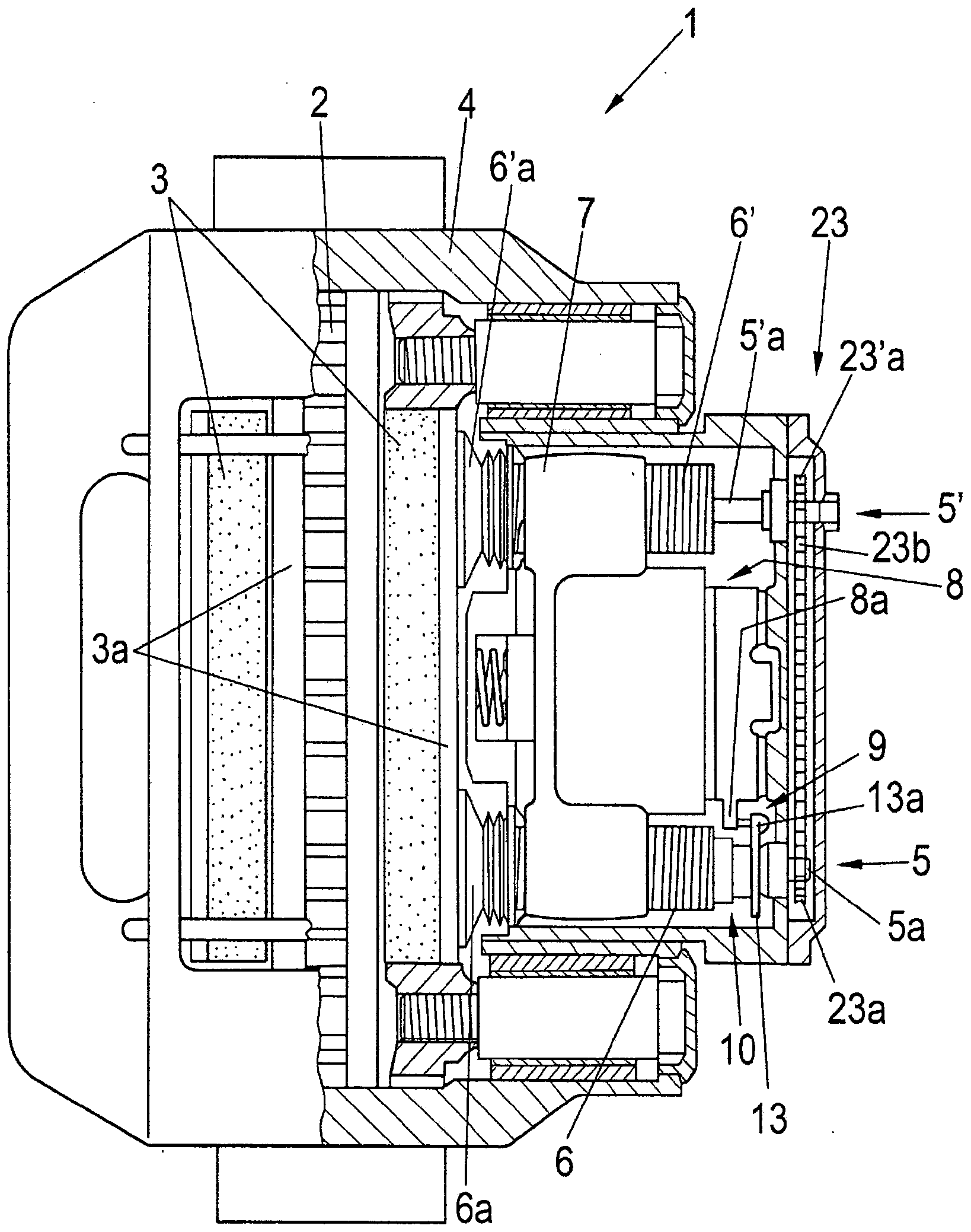
[0048] figure 1 A schematic sectional view of an embodiment of a disc brake according to the invention is shown.

[0049]The disc brake 1 is shown here in the embodiment of a double-rod brake comprising two screw units 5 , 5 ′ with threaded tubes 6 , 6 ′. The brake caliper 4 , designed here as a floating caliper, straddles the brake disk 2 , on which a brake lining 3 with a brake lining carrier 3 a is provided on both sides. The pressure-side brake lining carrier 3 a is connected to the screw unit 5 , 5 ′ at the end of the threaded tube 6 , 6 ′ via a pressure plate 6 a , 6 ′ a. The other brake lining carrier 3 a on the reactive side is fastened in the brake caliper 4 on the other side of the brake disc. The threaded pipes 6 , 6 ′ are respectively rotatably arranged in the cross member 7 . This crosspiece 7 and thus also the threaded tubes 6 , 6 ′ can be actuated by means of a pressing device, here a swivel lever 8 , the axis of rotation of which is perpendicular to the axis...


PUM


Abstract

A wear adjustment device is provided for the adjusting friction surface wear on a brake pad and a brake disc of a disc brake having a brake application device, preferably with a rotary lever. The wear adjustment device can be coupled on the drive side to the brake application device, and on the output side to a spindle unit. A respective rolling body arrangement is axially arranged on both sides of a drive element, one of which is designed as a roller bearing and one is designed as a ball ramp coupling. A central shaft is coupled to the ball ramp coupling and has an output interface for coupling to the spindle unit. A radial freewheel is coupled to the ball ramp coupling by an overload spring unit and to the central shaft. A directionally-dependent torque device is provided, along with a housing in which the drive element, the rolling body arrangements, the overload spring unit, the radial freewheel, the central shaft and the directionally-dependent torque unit are arranged.

Description

technical field [0001] The invention relates to a wear adjustment device for a disc brake, in particular a disc brake for a motor vehicle, according to the preamble of claim 1 . The invention also relates to a corresponding disc brake. Background technique [0002] Vehicles and certain technical equipment often use friction brakes in order to convert kinetic energy. Disk brakes are preferred here, especially in the field of passenger cars and commercial vehicles. In a typical construction of a disc brake, the disc brake consists of a brake caliper with an internal mechanism, usually also two brake linings and a brake disc. The cylinder force is introduced into the internal mechanism by means of a pneumatically operated cylinder, which is amplified by an eccentric and transmitted as a pressing force to the brake lining and brake disc via a threaded rod, in this case via a threaded rod Compensates for brake disc and brake lining wear. [0003] A pressing force acts on the ...

Claims


Application Information

Patent Timeline
Patent Type & Authority Applications(China)
IPC IPC(8): F16D65/56
CPCF16D2125/26B60T1/065F16D65/52F16D65/567F16D65/568F16D2125/32F16D65/42F16D2065/386
Inventor R·韦伯T·埃希勒P·哈贝尔-京特纳I·内斯姆亚诺维奇
Owner KNORR-BREMSE SYST FUER NUTZFAHRZEUGE GMBH
Why Eureka
Try Eureka