

Gantry type perforating machine tool
A gantry type and gantry technology, which is applied in manufacturing tools, boring/drilling, drilling/drilling equipment, etc., can solve problems such as difficulty in ensuring normal accuracy requirements, adverse effects of machine tool components, and shortening machine tool life. Achieve increased efficiency and flexibility, reduced adverse effects, and extended life
- Summary
- Abstract
- Description
- Claims
- Application Information
AI Technical Summary
Problems solved by technology
Method used
Image

Examples
Embodiment Construction
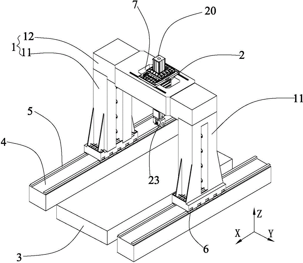
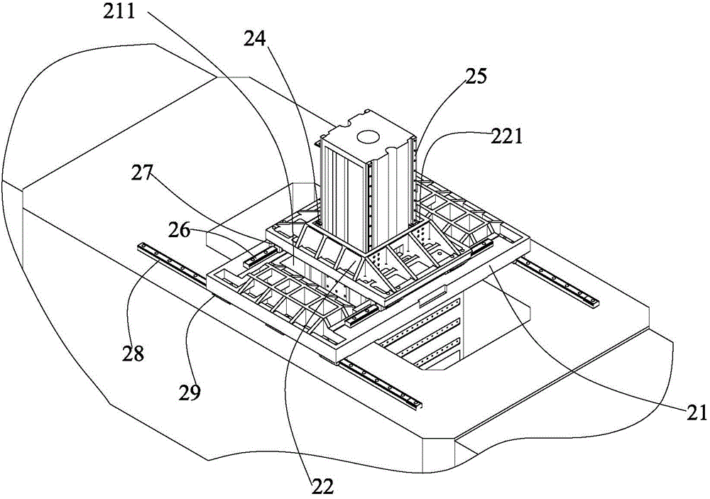
[0022] The gantry type hole making machine tool according to the present invention will be described in detail below with reference to the accompanying drawings.
[0023] refer to figure 1 and figure 2 According to the gantry type hole-making machine tool of the present invention, it comprises: a gantry frame 1 with two gantry columns 11 and a gantry beam 12 connecting the upper parts of the two gantry columns 11, the central position of the gantry beam 12 being provided with a through hole 7 along the Z direction ; Hole-making operation unit 2; central workbench 3, which is arranged under the gantry beam 12, for carrying workpieces; Located on the two bases 4; two sets of fourth guide rails 5 are respectively fixed on the two bases 4 along the X direction; and two sets of fourth sliders 6 are respectively fixed on the lower surfaces of the two gantry columns 11 along the X direction , are respectively slidably connected to two sets of fourth guide rails 5, so as to move th...
PUM
 Abstract
Description
Claims
Application Information