On-line measurement method for axis orbit of main shaft under cutting condition of numerical control lathe

A technology of CNC machine tools and shaft center trajectory, which is applied in the direction of measuring/indicating equipment, manufacturing tools, metal processing equipment, etc., can solve the problems of increasing rotation error calculation error, ineffective separation, poor signal consistency, etc., and achieve online measurement The problem of speed, satisfying the effect of fast separation

Active Publication Date: 2015-03-11
XI AN JIAOTONG UNIV
View PDF7 Cites 29 Cited by
  • Summary
  • Abstract
  • Description
  • Claims
  • Application Information

AI Technical Summary

Problems solved by technology

The three-point method is a representative of the multi-measuring point method. It can separate the rotational motion error of the main shaft through the information measured by three displacement sensors arranged at a specific angle on the circumference without affecting the work of the main shaft, which meets the basic requirements of online measurement of the rotational error. conditions, but the main disadvantage of the three-point method is that it cannot effectively separate the first-order harmonic component in the rotation error from the first-order harmonic component caused by the eccentric installation of the tested part. At the same time, the tolerable error range of the sensor distribution angle is very small. If there is an error in the process, it will easily cause harmonic suppression on certain orders, so the sensor distribution angle needs to be

Method used


Image

  • On-line measurement method for axis orbit of main shaft under cutting condition of numerical control lathe
  • On-line measurement method for axis orbit of main shaft under cutting condition of numerical control lathe
  • On-line measurement method for axis orbit of main shaft under cutting condition of numerical control lathe

Examples


Embodiment Construction

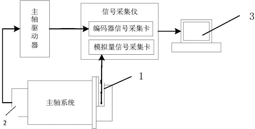
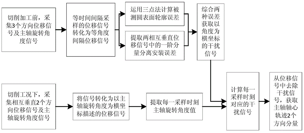
[0029] see Figure 1-3 , the on-line measurement method of the spindle axis track under the cutting condition of the CNC machine tool of the present invention comprises the following steps:

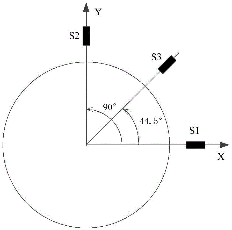
[0030] 1) On the surface of the measured circle of the spindle of the CNC machine tool, the first, second, and third displacement sensors S1, S2, and S3 for measuring the displacement signals of the measured surface are installed at a specific angle perpendicular to the axis along the circumferential direction of the spindle, and the first 2. The installation angle selection principle of the second and third displacement sensors S1, S2, and S3 is: in the effective order of the surface contour error of the measured circle, no harmonic suppression other than the first-order harmonic is caused. At the same time, the first and second The installation angle of the displacement sensors S1 and S2 is 90°; among them, a sensor bracket 1 is provided in the circumferential direction of the main axis...


PUM


Abstract

The invention relates to an on-line measurement method for an axis orbit of a main shaft under cutting condition of a numerical control lathe. The on-line measurement method comprises the following steps of arranging three displacement sensors on a to-be-measured circular surface along the circumferential direction of the main shaft, collecting displacement signals and main shaft rotary angle signals before cutting, converting into rotary angle interval sampling signals, adopting a three-point method to separate the contour error of the to-be-measured circular surface, extracting the displacement signals of the two vertical displacement sensors, and calculating the installation eccentric error; according to the contour error and the installation eccentric error, obtaining an interference signal guided by the to-be-measured circular surface; under the cutting condition, adopting an interpolation method to calculate the interference signal corresponding to the main shaft rotary angle signal, removing the interference signal from the displacement signal under the cutting condition, and obtaining the axis orbit of the main shaft. The method has the advantages that the influence on the separation calculation by the speed fluctuation of the main shaft is avoided, the requirements of separation accuracy and rotary error quick separation are met, and the on-line quick separation of the rotary error is realized.

Description

technical field [0001] The invention belongs to the field of industrial equipment operation state monitoring and fault diagnosis, and in particular relates to an online measurement method for the axis track of a spindle under the cutting condition of a numerically controlled machine tool. Background technique [0002] With the continuous development of science and technology, CNC machine tools, as an important processing equipment, are developing in the direction of high speed, high precision and high efficiency. The performance of the spindle of the CNC machine tool has a direct impact on the machining accuracy and stability of the machine tool, especially in the field of high-speed machining, the quality of the spindle motion performance is an important factor affecting the processing quality. [0003] The reduction of the motion performance of the CNC machine tool spindle can be manifested as the increase of the spindle motion error; the motion error of the spindle mainly...

Claims


Application Information

Patent Timeline
IPC IPC(8): B23Q17/00
CPCB23Q17/00
Inventor 陶涛徐新平梅雪松孙挪刚刘磊
Owner XI AN JIAOTONG UNIV
Why Eureka
Try Eureka