Thermal decomposition device of oil field waste

A technology for thermal decomposition of oilfield waste, which is applied in pyrolysis treatment of sludge and mining wastewater treatment, etc. It can solve the problems of small effective contact area and low heat transfer efficiency

Inactive Publication Date: 2015-03-11
JEREH ENERGY SERVICES
View PDF5 Cites 104 Cited by
  • Summary
  • Abstract
  • Description
  • Claims
  • Application Information

AI Technical Summary

Problems solved by technology

Due to the small effective contact area between the heating chamber and the flue g

Method used


Image

  • Thermal decomposition device of oil field waste
  • Thermal decomposition device of oil field waste
  • Thermal decomposition device of oil field waste

Examples


Embodiment Construction

[0024] The core of the present invention is to disclose a thermal decomposition device to achieve the purpose of improving the heat exchange efficiency of the thermal decomposition device. Hereinafter, an embodiment will be described with reference to the drawings. In addition, the examples shown below do not limit the content of the invention described in the claims in any way. In addition, all the contents of the configurations shown in the following embodiments are not limited to be essential to the solution of the invention described in the claims.

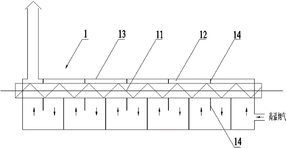
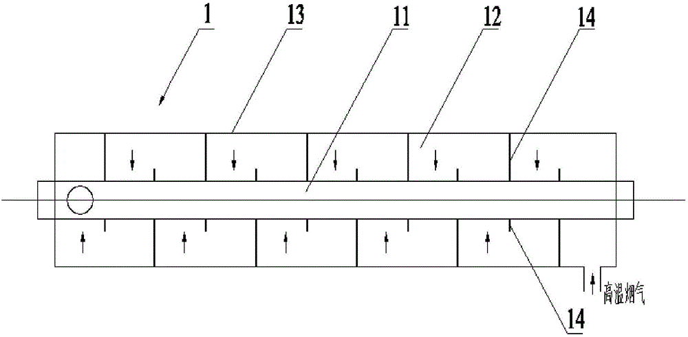
[0025] see figure 1 and figure 2 The shown thermal decomposition device for oil field waste, the thermal decomposition device 1 for oil field waste includes a housing 13, a flue is arranged inside the housing 13, the heating chamber is isolated from the flue, and the housing 13 A plurality of partitions 14 are arranged on the inner wall, and the plurality of partitions 14 make the flue a serpentine structure.

[0026] In ...


PUM


Abstract

The embodiment of the invention discloses a thermal decomposition device of oil field wastes. The thermal decomposition device comprises a casing, wherein a flue and a heating cavity are formed inside the casing; the heating cavity is isolated from the flue. The oil field waste thermal decomposition device is characterized in that a plurality of partitioning plates are arranged on the inner wall of the casing; the flue is of a snakelike structure through the adoption of the partitioning plates. Through the adoption of the partitioning plates on the inner wall of the casing of the thermal decomposition device disclosed by the invention, the flue inside the casing is of the snakelike structure, so that the flowing direction and the flowing speed of fume are changed, the turbulent flow effect is improved, the retention time is prolonged, and the heat exchange efficiency of the heating cavity and the fume is improved.

Description

technical field [0001] The invention relates to the technical field of oilfield waste treatment, in particular to a thermal decomposition device for oilfield waste. Background technique [0002] As the country intensifies the development of unconventional energy sources such as shale gas, waste oil-based mud and oily cuttings are continuously produced and accumulated in large quantities. The oily cuttings produced by a single well during the drilling stage are about 300-500 tons, of which oily substances Accounted for 25-30%. [0003] In oil and gas exploration, development and production, improper disposal of waste oil-based mud and oily drilling cuttings will cause serious pollution of water resources, soil, etc., and restrict development progress. Therefore, the harmless treatment of oil-based mud and oily drilling cuttings has generally received attention. Countries around the world have done a lot of work on the toxicity analysis, environmental impact assessment and tr...

Claims


Application Information

Patent Timeline
IPC IPC(8): C02F11/10C02F103/10
CPCC02F11/10C02F2103/10
Inventor 胡天勇梁仁刚何茂金闫亚丽林慧丽麻军峰曲忠臣陈开军
Owner JEREH ENERGY SERVICES
Why Eureka
Try Eureka