
Automobile glass heating method and heating device thereof

A technology of automobile glass and heating method, applied in the field of heating of automobile glass and heating device of automobile glass, can solve the problems of space channeling temperature of heating furnace, control of unfavorable convection heating, reduction of utilization rate, etc., to ensure stability and heating The effect is uniform and stable, and the effect of high energy consumption is solved

Active Publication Date: 2015-03-11
FUJIAN WANDA AUTOMOBILE GLASS IND
View PDF5 Cites 7 Cited by
  • Summary
  • Abstract
  • Description
  • Claims
  • Application Information

AI Technical Summary

Problems solved by technology

[0007] (1) It may cause "temperature shifting" in the furnace
[0008] Since the two sets of glass plates are alternately loaded and heated differently, the ambient temperature of the two sets of glass plates will be different during the heating process, which may cause "temperature shifting" between different spaces in the heating furnace, resulting in that the two sets of glass plates are not at the expected temperature. to heat
[0009] (2) The glass moves left and right during the transmission process
[0010] The convection heating introduced in the patent uses the airflow in the vertical relative direction to assist the heating, which may cause the position of the glass in the heating furnace to fluctuate from left to right, which cannot ensure the stability of the glass position during final molding, and may easily cause glass fragments during molding
[0011] (3) It is difficult to realize the heating of coated glass
Thus, the increase in convective heating of the upper coated surface 90 provides the required balance such that the two surfaces can be heated at the same rate and at the same temperature so that during its heating the glass remains is flat”, but combined with the claims of the patent, the patent only provides three convection heating methods: 1) only the upper convection heating; 2) only the lower convection heating; 3) both the upper and lower to provide convection Heated, but with the same flow rate of pressurized air
[0014] For a pair of glass plates such as a large piece coated on one side and a small piece uncoated, the patent does not specifically mention the relationship between the large coated surface and the non-coated surface and the relationship between the pressurized air flow rates on both sides of the small piece. Text description, it is also difficult for those skilled in the art to realize
[0015] (4) No specific process parameters mentioned, difficult to realize
[0016] Although the patent claims to protect the heating method and equipment, the patent as a whole is more focused on the introduction of the heating furnace. It only provides the heating method for the method, and does not mention the specific heating parameters / process ideas. It may be based on this in actual production. The heating method mentioned in the patent is difficult to achieve the desired effect
[0017] (5) Convective hot air nozzle structure not involved
[0018] According to the content disclosed in the patent, the hot air flow is directly supplied from the orifice of the hot air distributor delivery pipe, such a design will cause the hot air to heat the glass plate vertically, when there is hot air flow above and below the glass plate, The impact of two airflows in opposite directions on the glass will easily cause the glass to bump during transmission. In addition, the direction of the airflow cannot be adjusted, which is not conducive to the control of convective heating in actual production.
[0019] (6) High energy consumption
[0020] The patent exemplifies a remote heating system to provide hot air into the heating furnace. The additional heating of the air will cause a large energy consumption, and there will inevitably be heat loss during the transmission process, and the utilization rate will decrease.

Method used


Image

  • Automobile glass heating method and heating device thereof
  • Automobile glass heating method and heating device thereof
  • Automobile glass heating method and heating device thereof

Examples


Embodiment Construction

[0043] The content of the present invention will be further described below in conjunction with the accompanying drawings.

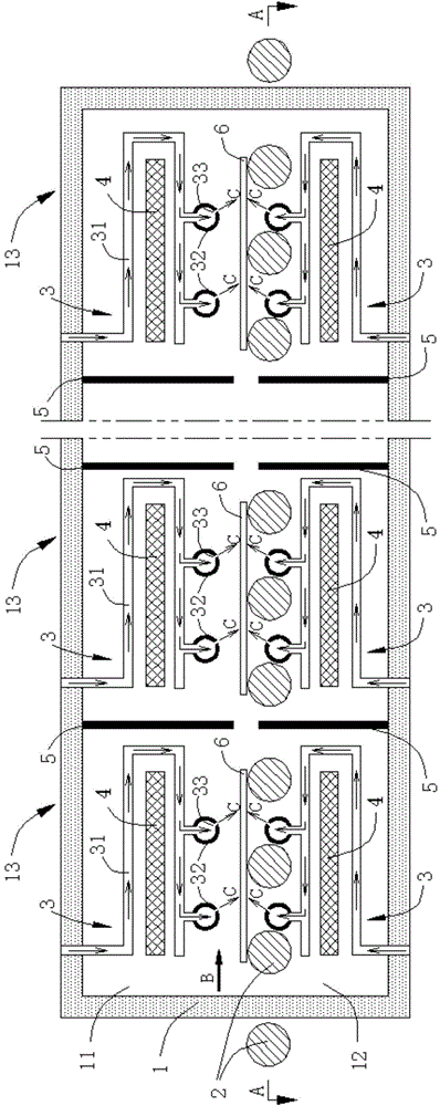
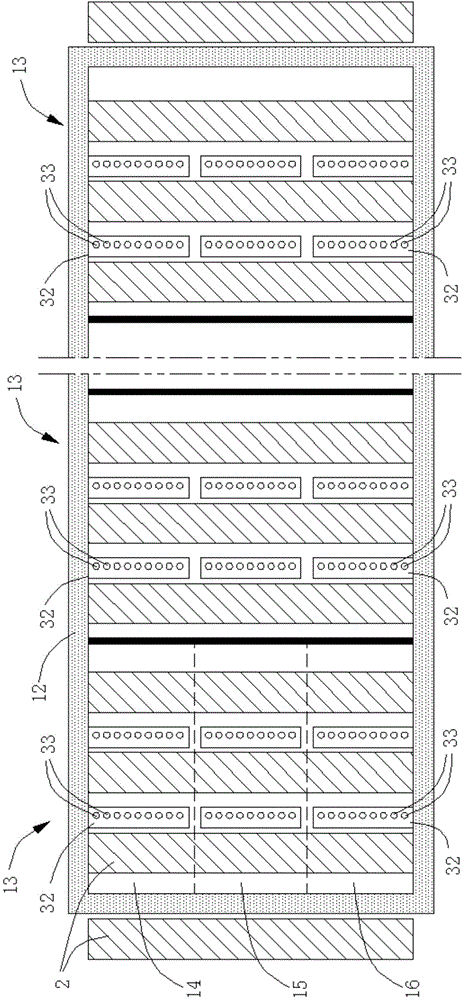
[0044] like Figure 1 to Figure 2 As shown, a method for heating automotive glass according to the present invention is used for heating coated glass and non-coated glass alternately loaded on the conveying roller 2, and the coated glass and non-coated glass are used to be paired together to form an interlayer Glass, the coated glass and non-coated glass are transported into the heating furnace 1 on the transmission roller 2 and passed out of the heating furnace 1 after being heated to a set temperature, and the heating furnace 1 has a transmission direction with the transmission roller 2 B parallel to the length direction and the width direction parallel to the axial direction of the conveying roller 2, the heating furnace 1 includes a furnace body upper part 11 and a furnace body lower part 12, and the heating furnace 1 passes through the furnace body ...


PUM


Abstract

The invention relates to the technical field of glass processing, and especially relates to an automobile glass heating method. The method is used for heating coated glass and non-coated glass alternatively loaded on a delivery roller, the coated glass and the non-coated glass are delivered on the delivery roller to a heating furnace, are heated to a preset temperature and are delivered out of the heating furnace, the heating furnace is divided by separator plates into a plurality of linearly arranged heating zones along the delivery direction of the delivery roller, the temperatures of the heating zones monotonously increase along the delivery direction of the delivery roller, and the convection heating air velocities of the heating zones are adjusted according to the automobile glass loaded in all the heating zones. The invention also provides an automobile glass heating device. The method and the device solve the temperature change problem in the furnace and the positioning problem of glass in order to make the glass uniformly and stably heated.

Description

Technical field: [0001] The invention relates to the technical field of glass processing, in particular to a heating method for automobile glass, especially a heating method for automobile glass before the forming operation of coated laminated glass for automobiles, and also provides a heating device for automobile glass. Background technique: [0002] Laminated glass for automobiles generally adopts the structure of glass + polymer + glass. We are used to calling the ones located outside the car large pieces, and the ones located inside the car called small pieces. Large pieces and small pieces often have different characteristics. For example, Different compositions, different thicknesses, different surface properties, and combinations thereof. In the prior art of laminated glass for automobiles, sometimes it is desired to heat the automobile glass first and then perform a forming operation or any other suitable operation. The heating of glass pairs with different characte...

Claims


Application Information

Patent Timeline
Patent Type & Authority Applications(China)
IPC IPC(8): C03C27/12
CPCC03B32/005
Inventor 尚贵才张金树林有雄陈恒福施家梅
Owner FUJIAN WANDA AUTOMOBILE GLASS IND
Learn More