A three-plate high energy dissipation viscous damping wall

A viscous damping wall and high energy consumption technology, which is applied in the direction of walls, building components, building structures, etc., can solve the problem that the viscous damping wall's shock absorption and energy consumption effect cannot reach the expected value, and it cannot be well adapted to site requirements. Problems such as transverse bending and deformation of the inner steel plate, to achieve the effect of increasing the effective contact area, strong energy dissipation capacity, and enhanced dissipation capacity

Active Publication Date: 2017-03-08
TONGJI UNIV ARCHITECTURAL DESIGN INST GRP CO LTD
View PDF6 Cites 0 Cited by
  • Summary
  • Abstract
  • Description
  • Claims
  • Application Information

AI Technical Summary

Problems solved by technology

[0004] However, the viscous damping wall with this structure will encounter the following problems in engineering applications: when the direction of the earthquake or wind load is inconsistent with the direction of the inner steel plate, the inner steel plate is prone to transverse bending deformation, which will lead to a decrease in the energy dissipation capacity of the damping wall , it will lead to complete destruction of the damping wall and loss of energy dissipation capacity; and the existing viscous damping wall is a fixed structure. During the construction process, when the building's seismic performance requirements for the damping wall change, it cannot be well adapted to the site requirements. As a result, the shock absorption and energy dissipation effect of the viscous damping wall cannot reach the expected value

Method used


Image

  • A three-plate high energy dissipation viscous damping wall
  • A three-plate high energy dissipation viscous damping wall
  • A three-plate high energy dissipation viscous damping wall

Examples


Embodiment

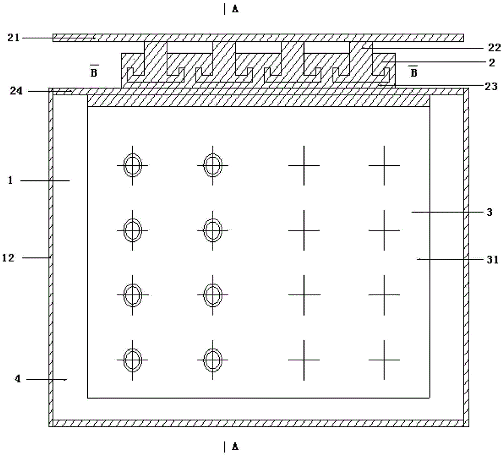
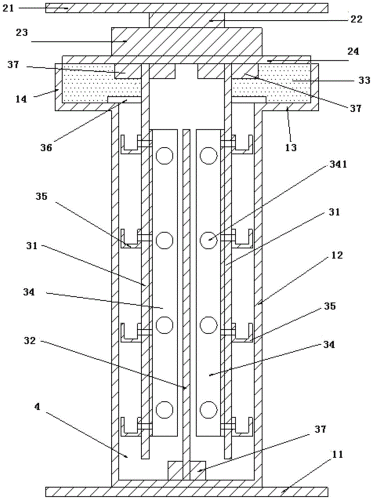
[0032] Such as figure 1 and figure 2 As shown, a three-plate viscous damping wall with high energy consumption is set between the upper and lower floor beams for shock absorption and energy dissipation of the building structure, including the wall 1 and the top seal 2, the upper floor beams, The top seal 2, the wall 1 and the lower floor beams are connected in sequence, the wall 1 and the top seal 2 are connected to form a wall sealing space, and the energy dissipation damping structure 3 is arranged in the wall sealing space, and the energy dissipation damping structure 3 includes The upper inner steel plate 31 and the lower inner steel plate 32, the upper inner steel plate 31 is provided with two pieces, which are rigidly connected with the top seal 2 respectively, and the lower inner steel plate 32 is arranged between the two upper inner steel plates 31, and is rigidly connected to the bottom of the wall body 1 catch.

[0033] The energy dissipation damping structure 3 ...


PUM


Abstract

The invention relates to a three-plate type high-energy-consumption viscous damping wall which is arranged between upper and lower floor surface beams and is used for vibration absorption and energy dissipation of a building structure. The three-plate type high-energy-consumption viscous damping wall comprises a wall body and a top sealing piece; the upper floor surface beam, the top sealing piece, the wall body and the lower floor surface beam are connected in sequence; a wall body sealing space is formed by connecting the wall body with the top sealing piece; an energy consumption damping structure is arranged in the wall body sealing space and the wall body sealing space is filled with viscous damping liquid; when a building floor has relative displacement, the energy consumption damping structure can slide in a viscous damping material of the wall body along the vertical direction of the wall body to generate a damping force, so that the energy of earthquakes or a wind load input structure is dissipated and a power reaction of the structure is reduced. Compared with the prior art, the three-plate type high-energy-consumption viscous damping wall has the advantages of strong energy consumption capability, stable performance, deformation resistance, stable output force, damage resistance and the like.

Description

technical field [0001] The invention relates to a damping wall, in particular to a three-plate viscous damping wall with high energy consumption. Background technique [0002] Passive control refers to a control method that does not require external energy, and relies on the installation of vibration-reducing devices such as isolation bearings, dampers or auxiliary systems (substructures) in the structure to isolate or reduce seismic energy and reduce the seismic response of the structure. . It mainly includes vibration isolation, vibration absorption and vibration reduction, energy consumption and vibration reduction and other forms. The energy dissipation and vibration reduction of structures is a form of passive control of structures. It is to install certain energy dissipation devices in specific parts of engineering structures, such as shock isolation pads, energy dissipation supports, energy dissipation shear walls, energy dissipation devices, etc. method to control ...

Claims


Application Information

Patent Timeline
Patent Type & Authority Patents(China)
IPC IPC(8): E04B1/98E04B2/00
Inventor 赵昕占茜郑毅敏石涛张鸿玮
Owner TONGJI UNIV ARCHITECTURAL DESIGN INST GRP CO LTD
Why Eureka
Try Eureka