Low-noise cutting device

A cutting device and low-noise technology, applied in the field of low-noise cutting devices, can solve the problems of low grooving efficiency, increased workload, high noise decibels, etc., to improve grooving efficiency, reduce workload, and increase reflection efficiency Effect

Active Publication Date: 2015-03-11
CHENGDU ZHIRONG ZHICHUANG INTPROP MANAGEMENT CO LTD
View PDF11 Cites 0 Cited by
  • Summary
  • Abstract
  • Description
  • Claims
  • Application Information

AI Technical Summary

Problems solved by technology

[0002] The hidden line layout is usually used for cable wiring in oil warehouses, that is, it is necessary to cut out the grooves for embedding line pipes on the wall or on the ground. For grooves with short width and length, manual operation is more convenient, but for grooves with large length and width, manual removal will increase the workload, consume a lot of energy, and the efficiency of groove removal is low; Groove picking also involves cutting both sides of the groove with a marble machine, and then using a hammer and drill to remove the concrete in the middle of the two cutting seams. The cutting can only be completed by applying a large thrust to the marble machine. In the process of use, the saw blade is often loose and the motor is idling.
[0003] Under the long-term use of the marble machine, because of the high decibel noise generated during cutting, the staff will have tinnitus after use, which will lead to a decrease in the efficiency of groove cutting and removal

Method used


Image

  • Low-noise cutting device
  • Low-noise cutting device
  • Low-noise cutting device

Examples


Embodiment 1

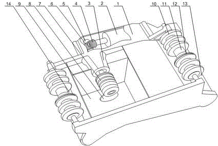
[0023] Such as Figure 1 to Figure 3 As shown, this embodiment includes a housing 1 and a motor 2 installed inside the housing 1. A movable cavity 9 with an open bottom is opened in the middle of the housing 1, and a bevel gear is fixedly arranged on the output end of the motor 2. A4, a rotating shaft 5 is installed in the housing 1, and a saw blade clamping head 7 is installed on one end of the rotating shaft 5, and the saw blade clamping head 7 is placed in the movable cavity 9, and the other end of the rotating shaft 5 is installed with a cone The bevel gear B6 matched with the gear A4; the saw blade clamping head 7 includes a nut 21, a plurality of clamping blocks 16 and movable blocks 19 that are slidably arranged on the rotating shaft 5, and between two adjacent clamping blocks 16 A gap 17 is left, and an annular groove 20 is oppositely arranged on two adjacent clamping blocks 16. The movable block 19 can move freely in the annular groove 20, and the movable block 19 is ...

Embodiment 2

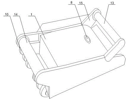
[0027] Such as figure 1 and figure 2 As shown, in this embodiment, on the basis of Embodiment 1, a rear armrest 14 is installed at one end of the housing 1, and two supporting plates 15 arranged in parallel are installed on the other end of the housing 1, and the two supporting plates 15 is connected by front armrest 13. When in use, the operator holds the movable handle and the fixed handle respectively to cooperate with a plurality of rollers 10 to push the movement of the housing 1, wherein the movable handle is installed between two support plates 15, when the movable handle is pressed down, the saw blade is cutting the wall Larger vibrations will be generated when the operator is in the body. Through the buffering effect of the two armrests, the impact of vibration on the hands of the operator is greatly reduced, further reducing the workload of the operator.

[0028] It also includes a fixed cylinder 3 installed on the housing 1 , and the rotating shaft 5 is rotatably...

Embodiment 3

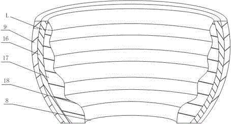
[0030] Such as image 3 As shown, the present embodiment is based on Embodiment 1. As a preference, the present invention sets the movable cavity 9 as a semicircular cavity, which increases the reflection efficiency of debris in the movable cavity 9 and accelerates the crushing process. chip discharge, improve the operator's slotting efficiency.


PUM


Abstract

The invention discloses a low-noise cutting device. The device comprises a shell and a motor, wherein the middle part of the shell is provided with a movable cavity with an open bottom; a saw blade clamping head is arranged in the movable cavity; the other end of the rotating shaft is provided with a bevel gear B which is matched with a bevel gear A; the movable cavity is provided with a through hole which is communicated with the exterior; the inner wall of the movable cavity is provided with a reflecting layer and foamed aluminum from top to bottom in sequence; the reflecting layer is provided with a plurality of connected annular reflecting bumps; distances L from the highest points of the reflecting bumps to the outer wall of the movable cavity increase along the direction from the open end of the movable cavity to the through hole. The reflection efficiency of scraps at the position is the highest, so that the scraps produced close to the through hole are quickly rebounded to the bottom of the movable cavity and finally discharged from the open end of the movable cavity. According to the device, the noise effect produced by cutting is reduced to the minimum, the scraps produced by the cutting are also quickly discharged, and the slot cutting efficiency is improved.

Description

technical field [0001] The invention relates to the field of petroleum machinery, in particular to a low-noise cutting device. Background technique [0002] The hidden line layout is usually used for cable wiring in oil warehouses, that is, it is necessary to cut out the grooves for embedding line pipes on the wall or on the ground. For grooves with short width and length, manual operation is more convenient, but for grooves with large length and width, manual removal will increase the workload, consume a lot of energy, and the efficiency of groove removal is low; Groove picking also involves cutting both sides of the groove with a marble machine, and then using a hammer and drill to remove the concrete in the middle of the two cutting seams. Only when a large thrust is applied to the marble machine can the cutting be completed. In the process of use, the saw blade often becomes loose and the motor runs idly. [0003] Under the long-term use of the marble machine, because ...

Claims


Application Information

Patent Timeline
Patent Type & Authority Applications(China)
IPC IPC(8): E04F21/00
Inventor 贺昶明
Owner CHENGDU ZHIRONG ZHICHUANG INTPROP MANAGEMENT CO LTD
Why Eureka
Try Eureka