a speed control clutch
A clutch and speed regulation technology, applied in the direction of machine/engine, coolant flow control, engine components, etc., can solve the problems of large machine wear, short life, low work efficiency, etc., to prolong the service life, save energy, and facilitate The effect of dismantling and repairing
- Summary
- Abstract
- Description
- Claims
- Application Information
AI Technical Summary
Problems solved by technology
Method used
Image
Examples
Embodiment 1
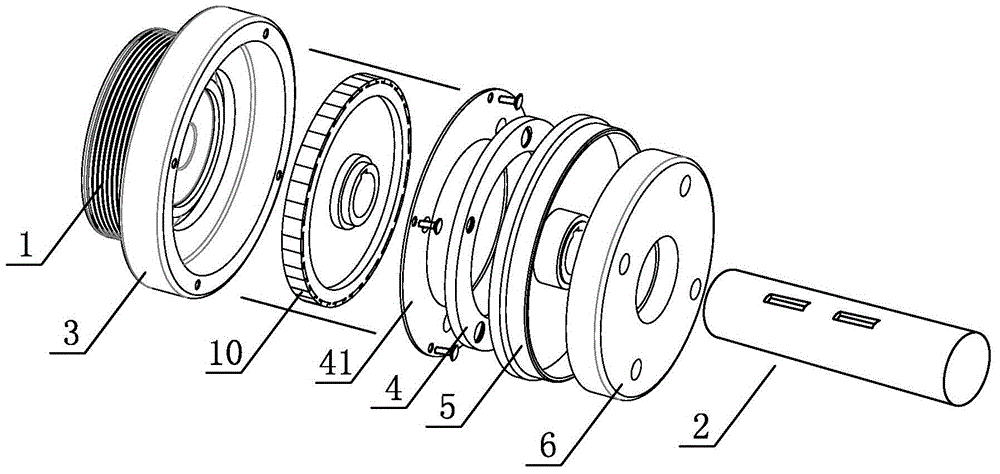
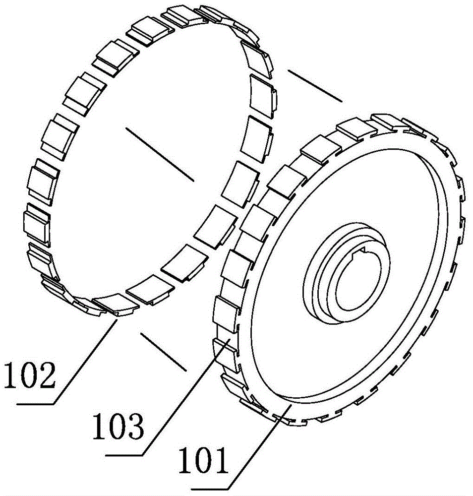
[0026] Such as figure 1 and 3 As shown, the speed regulating clutch of this embodiment is used to transmit the power of the pulley 1 to the power input shaft 2 of the equipment, the connection hole of the pulley 1 is sleeved on the front end of the power input shaft 2 through a bearing, and the pulley 1 faces one side of the equipment It is the right side of the belt pulley 1, the fixed disk 3 is installed on the right side, the fixed disk 3 is fixedly connected with the pulley 1 with bolts, the right side of the fixed disk 3 has a groove, the inside of the groove accommodates the magnet disk 10, the magnet disk 10 Fixed on the power input shaft 2 by a flat key, the magnet disc 10 can rotate in the groove along with the power input shaft 2, and the groove side of the groove is fixedly connected to the suction disc 4 through the spring piece 41, which has two inner and outer circles Screw holes, the screw holes of the outer ring are used to thread the spring sheet 41 and the f...
Embodiment 2
[0032] Such as Figure 4-5As shown, the difference between this embodiment and Embodiment 1 is that there is an installation groove 51-1 in the cavity on the right side of the transmission disc 5-1, the installation groove 51-1 is an annular groove, and a second spring is installed inside it. The sheet 91-1 and the second suction plate 9-1, the second spring sheet 91-1 has two rings of screw holes inside and outside, and the inner ring screw holes are used to screw the second spring sheet 91-1 and the installation groove 51-1, The screw holes in the outer ring are used to bolt the second spring piece 91-1 and the second suction plate 9-1, and the second coil 8 facing the second suction plate 9-1 is also arranged in the iron core 6-1. -1, when the second coil 8-1 is energized, a magnetic field is generated, which can attract the second engaging disk 9-1 to the iron core 6-1.
[0033] The control method of the speed regulating clutch in this embodiment for three-speed equipment...
Embodiment 3
[0038] Such as Figure 6-7 As shown, the difference between this embodiment and Embodiment 1 is that the magnet disk 10-2 is mounted on the power input shaft 2-2 through a bearing, and the right side of the magnet disk 10-2 is provided with a second spring piece 91-2 And the second suction plate 9-2, the second spring piece 91-2 has two circles of screw holes inside and outside, the outer circle screw hole is used for threaded connection of the second spring piece 91-2 and the magnet disc 10-2, the inner circle screw hole The bolts are used to connect the second spring piece 91-2 and the second suction disk 9-2, and the iron core 6-2 is further provided with a second coil 8-2 facing the second suction disk 9-2.
[0039] The control method of the speed regulating clutch in this embodiment for three-speed equipment is as follows: start the motor driving the pulley 1-2, and then control the speed regulating clutch according to the speed requirement of the equipment. The specific ...
PUM
 Abstract
Description
Claims
Application Information
 - R&D
- Intellectual Property
- Life Sciences
- Materials
- Tech Scout
- Unparalleled Data Quality
- Higher Quality Content
- 60% Fewer Hallucinations
Browse by: Latest US Patents, China's latest patents, Technical Efficacy Thesaurus, Application Domain, Technology Topic, Popular Technical Reports.
© 2025 PatSnap. All rights reserved.Legal|Privacy policy|Modern Slavery Act Transparency Statement|Sitemap|About US| Contact US: help@patsnap.com


