Multifunctional transmission case housing of agricultural vehicle

A multi-functional, transmission box technology, applied in the direction of transmission components, transmission parts, components with teeth, etc., can solve the problems that cannot meet the multi-interface structure design, etc., and achieve the effect of reasonable structure layout

Inactive Publication Date: 2015-03-11
CHONGQING XIANYOU TECH DEV
7 Cites 0 Cited by

AI-Extracted Technical Summary

Problems solved by technology

[0003] At present, in view of the need for multiple external power interfaces for agricultural ...

Abstract

The invention provides a multifunctional transmission case housing of an agricultural vehicle. The multifunctional transmission case housing comprises an upper housing and a lower housing which are tightly connected through a bolt; an input shaft hole and an output shaft hole are formed between the upper housing and the lower housing, wherein the input shaft hole comprises a front input shaft hole and a rear input shaft hole; the output shaft hole comprises a front output shaft hole and a rear output shaft hole; the input shaft hole and the output shaft hole are arranged in the same level and both extend toward the outer side of the case body to form bearing blocks; an assistant support is arranged at the inner bottom part of the housing; a bearing mounting seat is arranged on the assistant support and is coaxial with the output shaft hole; the assistant support extends to the inner side of the case body to be equipped with a medium bearing block, and an independent bearing block is arranged corresponding to the medium bearing block, wherein the medium bearing block and the independent bearing block are coaxially designed; the mounting planes of the medium bearing block and the independent bearing block are lower than the mounting planes of the input shaft hole and the output shaft hole.

Application Domain

Transmission elementsGearing details

Technology Topic

Agricultural engineeringMultiple function

Image

  • Multifunctional transmission case housing of agricultural vehicle
  • Multifunctional transmission case housing of agricultural vehicle
  • Multifunctional transmission case housing of agricultural vehicle

Examples

  • Experimental program(1)

Example Embodiment

[0066] The embodiments of the present invention are described below through specific specific examples, and those skilled in the art can easily understand other advantages and effects of the present invention from the contents disclosed in this specification. The present invention can also be implemented or applied through other different specific embodiments, and various details in this specification can also be modified or changed based on different viewpoints and applications without departing from the spirit of the present invention.
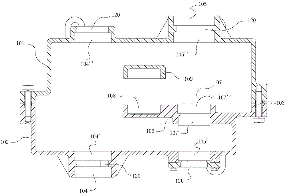
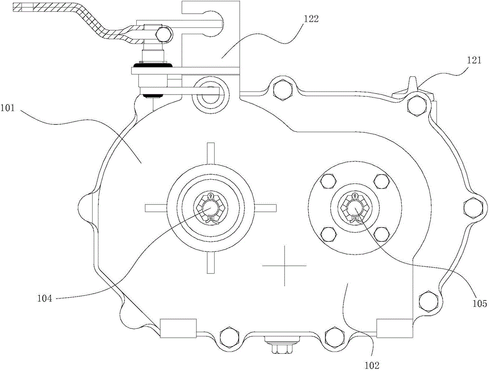
[0067] Attached according to the manual figure 1 , 2 As shown in the figure, a multi-functional transmission case casing for agricultural vehicles includes an upper casing 101 and a lower casing 102. The upper and lower casings 101 and 102 are fastened and connected by bolts 103, and the upper and lower casings are provided with Input shaft hole 104 and output shaft hole 105, input shaft hole 104 includes front input shaft hole 104' and rear input shaft hole 104", output shaft hole 105 includes front output shaft hole 105' and rear output shaft hole 105", input shaft The hole 104 and the output shaft hole 105 are arranged on the same horizontal plane. Both the input shaft hole 104 and the output shaft hole 105 are provided with bearing seats extending to the outside of the casing. The inner bottom of the casing is also provided with an auxiliary support 106. The auxiliary support 106 is provided with a bearing installation The seat 107, the bearing mounting seat 107 on the auxiliary support 106 is arranged coaxially with the output shaft hole 105, the auxiliary support 106 extends to the inside of the box and is provided with an intermediate bearing seat 108, corresponding to the intermediate bearing seat 108 is provided with an independent bearing seat 109, the intermediate bearing The seat 108 and the independent bearing seat 109 are coaxially designed, and the mounting surfaces of the intermediate bearing seat 108 and the independent bearing seat 109 are lower than the mounting surfaces of the input shaft hole 104 and the output shaft hole 105 .
[0068] The bearing housing 107 on the auxiliary support 106 includes a front bearing housing 107' and a rear bearing housing 107".
[0069] The front input shaft hole 104' is provided with two bearing mounting seats, and an oil seal groove 120 is provided between the bearing mounting seats.
[0070] The rear output shaft hole 105" is provided with two bearing mounting seats, and an oil seal groove 120 is provided between the bearing mounting seats.
[0071] A bearing mounting seat is provided on the rear input shaft hole 104", and an oil seal groove 120 is provided on the outer side of the bearing mounting seat.
[0072] A bearing mounting seat is provided on the front output shaft hole 105', and an oil seal groove 120 is provided on the outer side of the bearing mounting seat.
[0073] An oil dipstick 121 is provided on the upper right side of the upper casing 101 .
[0074] A brake rocker arm mounting seat 122 is provided on the upper left side of the upper casing 101 .
[0075] According to the attached image 3It can be known that a multifunctional transmission box for agricultural vehicles includes a box body 1, a power input shaft 2 is arranged in the box body 1, the input shaft 2 penetrates the box body 1, the input end is connected to the power equipment, and the input shaft 1 is connected to the input end and the box body. 1. There are two sets of deep groove ball bearings 3, and an oil seal 4 is arranged between the two sets of deep groove ball bearings 3. The output end cooperates with the box body 1 through the deep groove ball bearing 5, extends to the outside, and is connected to the pulley 6 to transmit the power to the outside. The input shaft 2 is supported on the casing 1 through the front input shaft hole 104' and the rear input shaft hole 104".
[0076] A gear 7 is also provided on the input shaft 2. The a gear 7 has no power transmission with the input shaft 2. The input shaft 2 is also fixedly provided with a combined gear 8. The combined gear 8 can be meshed with the upper end face of the a gear 7. The a gear 7 Meshing with the b gear 9, the b gear 9 is arranged on the motor output shaft 10, the motor output shaft 10 is arranged in parallel with the input shaft 2, and the motor output shaft 10 is supported by the front output shaft hole 105' and the front bearing seat 107'. The end face of the motor output shaft 10 is arranged inside the box body 1, and is fixed on the box body 1 through the deep groove ball bearing 11. A spacer 12 is provided between the deep groove ball bearing 11 and the upper surface of the b gear 9. The spacer 12 Sleeve on the motor output shaft 10. The output end of the motor output shaft 10 passes through the box body 1 and is on the same side as the input shaft 2. The output shaft of the motor output shaft 10 is connected to the pulley 13 through a flat key, so that the power can be transmitted to other equipment through the pulley 13. The motor output shaft 10 passes through the box body 1 and is matched by the deep groove ball bearing 14. The outer end of the deep groove ball bearing 14 is provided with an end cover 15 which is fixed on the box body 1 by bolts. There are oil seals 16.
[0077] The input shaft 2 drives the combined gear 8 to rotate, the combined gear 8 meshes with the end face of the a gear 7, and transmits the power to the a gear 7, the a gear 7 transmits the power to the b gear 9 that meshes with it, and the b gear 9 drives the motor output shaft 10 Rotating, the motor output shaft 10 drives the pulley 13 to rotate, and the pulley 13 transmits the power to the external equipment.
[0078] The upper part of the input shaft 2 is also fixed with a combined gear hub 17 and a combined gear sleeve 18. The upper and lower parts of the combined gear hub 17 and the combined gear sleeve 18 are respectively provided with c main power gear 19 and d main power gear 20, c main power gear 19 The main power gear 20 and the input shaft 2 are not connected, and rotate independently of each other. c main power gear 19 meshes with e slave power gear 21, e slave power gear 21 is arranged on the output shaft 22, the output shaft 22 is parallel to the input shaft 2, and the output shaft 22 passes through the rear bearing seat 107" and the rear output shaft hole 105" Support, the output shaft 22 and the motor output shaft 10 are axially arranged on the same straight line. One end of the output shaft 22 is disposed inside the casing 1 through a bearing, and is disposed away from the motor output shaft 20 . One end of the output shaft 22 extends to the outside of the box body 1 , and two sets of deep groove ball bearings 23 are arranged in cooperation with the box body 1 , and an oil seal 24 is arranged between the two sets of deep groove ball bearings 23 . The output end of the output shaft 22 is provided with an output receiving plate 25 , and a steel pad is fixed on the output receiving plate 25 .
[0079] The input shaft 2 drives the combined gear hub 17 to rotate, the combined gear sleeve 18 meshes with the c main power gear 19, and drives the c main power gear 19 to rotate, and the c main power gear 19 drives the meshed e slave power gear 21 to rotate, and e slave power The gear 21 drives the output shaft 22 to rotate forward, and the output shaft 22 transmits the power to the outside.
[0080] d The main power gear 20 meshes with the f slave power gear 26, the f slave power gear 26 is arranged on the driven shaft 27, the two ends of the driven shaft 27 are supported on the inner side of the casing 1 through deep groove ball bearings, and the driven shaft 27 is arranged in the Between the input shaft 2 and the output shaft 22 , the driven shaft 27 is parallel to the input shaft 2 and the output shaft 22 , and the driven shaft 27 is supported by the intermediate bearing seat 108 and the independent bearing seat 109 . The driven shaft 27 is also provided with a g driven power gear 28 . The g driven power gear 28 meshes with the h driven power gear 29 , and the h driven power gear 29 is provided on the output shaft 22 . A spacer 30 is provided between the e driven power gear 21 and the h driven power gear 29 , and the spacer 30 is sleeved on the output shaft 22 .
[0081] The input shaft 2 drives the combined gear hub 17 to rotate, the combined gear sleeve 18 meshes with the d main power gear 20, and drives the d main power gear 20 to rotate, and the d main power gear 20 drives the meshed f slave power gear 26 to rotate, and f slave power The gear 26 drives the driven shaft 27 to rotate forward, the driven shaft 27 drives the g-slave power gear 28 to rotate, the power gear g28 drives the h-slave power gear 29 meshed with it, the power gear h29 drives the output shaft 22 to reverse, and the output shaft 22 will Power is transmitted to the outside.
[0082] The above-mentioned embodiments merely illustrate the principles and effects of the present invention, but are not intended to limit the present invention. Anyone skilled in the art can modify or change the above embodiments without departing from the spirit and scope of the present invention. Therefore, all equivalent modifications or changes made by those with ordinary knowledge in the technical field without departing from the spirit and technical idea disclosed in the present invention should still be covered by the claims of the present invention.

PUM

no PUM

Description & Claims & Application Information

We can also present the details of the Description, Claims and Application information to help users get a comprehensive understanding of the technical details of the patent, such as background art, summary of invention, brief description of drawings, description of embodiments, and other original content. On the other hand, users can also determine the specific scope of protection of the technology through the list of claims; as well as understand the changes in the life cycle of the technology with the presentation of the patent timeline. Login to view more.

Similar technology patents

Ventilating power distribution cabinet

InactiveCN105703226AReasonable structure layoutimprove communication skills
Owner:欧志洪

Rehabilitation training device

InactiveCN109011369Agood recoveryReasonable structure layout
Owner:安徽健朗医疗器械有限公司

Novel longitudinal fully-through maintenance channel for water gate

ActiveCN107740382AReasonable structure layoutStructural layout is safe and reliable
Owner:广东省水利电力勘测设计研究院有限公司

U-shaped lock

PendingCN113090130AReasonable structure layoutEasy to assemble, produce and use
Owner:温州金钥匙锁业有限公司

Driving assembly of crow bar bending bicycle

ActiveCN113799903AReasonable structure layoutAvoid Part Conflicts
Owner:慈溪市神驹节能科技有限公司

Classification and recommendation of technical efficacy words

  • Reasonable structure layout

Method and device for detecting surface defects and thickness of semiconductor sheet material

ActiveCN103543162AReasonable structure layouteasy maintenance
Owner:CHINA UNIV OF MINING & TECH

Upper grabbing line tensioning device

InactiveCN105686216ASmall footprintReasonable structure layout
Owner:山东省雅尚名品家居有限公司

Automatic down lamp assembling equipment

PendingCN111002030AIncrease productivityReasonable structure layout
Owner:江苏阳铭互联智能系统有限公司

Controller of automatic reclosing lock

ActiveCN103065884Asmall heightReasonable structure layout
Owner:乾友科技有限公司

Air conditioner air outlet air path regulating and control mechanism

ActiveCN109955679AImprovement effectReasonable structure layout
Owner:MIND ELECTRONICS APPLIANCE CO LTD
Why Eureka
Try Eureka