
Winding tubular heat exchanger provided with vertical partition plate in cavity

A winding tube type, vertical baffle technology, applied in heat exchanger types, indirect heat exchangers, tubular elements, etc., can solve the problem of uneven distribution of gas and liquid, and achieve improved heat exchange performance and high strength stress. , the effect of increasing the effective heat exchange area

Inactive Publication Date: 2015-03-11
CHINA NAT OFFSHORE OIL CORP +1
View PDF7 Cites 17 Cited by
  • Summary
  • Abstract
  • Description
  • Claims
  • Application Information

AI Technical Summary

Problems solved by technology

The wound heat exchanger described in this invention has a distributor for distributing the liquid in the external space, which is beneficial to reduce the uneven distribution of gas and liquid at the top inlet of the shell side cavity, but it cannot solve the problem of the shell side under the sea sloshing condition. The problem of uneven gas-liquid distribution in the middle and bottom of the cavity

Method used


Image

  • Winding tubular heat exchanger provided with vertical partition plate in cavity
  • Winding tubular heat exchanger provided with vertical partition plate in cavity

Examples


Embodiment Construction

[0018] The present invention will be further described below in conjunction with the accompanying drawings, but the present invention is not limited to the following embodiments.

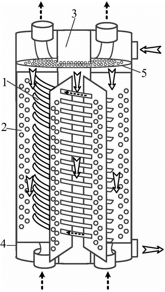
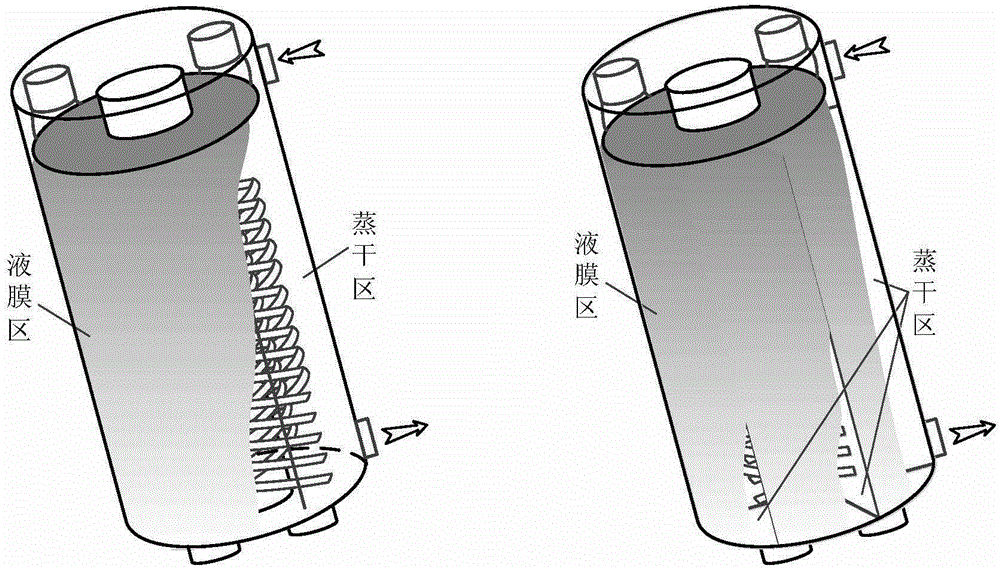
[0019] Such as figure 1 As shown, it is a wound tube heat exchanger with a vertical partition in the cavity of the present invention, which includes a shell 1 and a central cylinder 3, wherein the central cylinder 3 is arranged in the cavity of the shell 1 to form an annular cavity . A plurality of winding tubes 1 are wound in the annular cavity for passing in fluid. There are a plurality of metal orifice plates 2 in the ring cavity, which are vertically arranged in the ring cavity and arranged symmetrically along the circumference of the central cylinder 3, and each layer of winding pipe 1 passes through the through holes on each metal orifice plate 2 to fix. One end of the metal orifice plate 2 is welded on the inner wall of the housing 4, and the other end is welded on the outer wall of the ce...


PUM

PropertyMeasurementUnit
Thicknessaaaaaaaaaa
Outer diameteraaaaaaaaaa

Abstract

The invention discloses a winding tubular heat exchanger provided with a vertical partition plate in a cavity. The winding tubular heat exchanger comprises a housing and a central barrel. The central barrel is arranged in the cavity of the housing to form an annular cavity. A plurality of winding tubes are winded in the annular cavity. A plurality of metal pore plates are arranged in the annular cavity and are vertically arranged in the annular cavity, and the winding tubes penetrate through the through holes formed in the metal pore plates. One end of each metal pore plate is connected to the inner wall of the housing, and the other end of each metal pore plate is connected to the outer wall of the central barrel. A gas-liquid even distributing device is arranged in the cavity between the metal pore plates and the top of the housing. The metal pore plates are vertically arranged in the cavity, so that one whole cavity is divided into a plurality of independent cavities, and refrigerants in the independent cavities do not flow into other cavities. Therefore, it can be ensured that liquid films of the housing-side refrigerants flowing into the independent cavities and an in-tube working medium inside the cavities perform full heat exchange, and the phenomenon that the refrigerants flow into other independent cavities due to hull inclination and then invalid heat exchange inside the original cavities is caused is avoided.

Description

technical field [0001] The invention relates to a coiled tube heat exchanger with vertical partitions arranged in a cavity, and belongs to the technical field of low temperature heat exchange. Background technique [0002] Spiral tube heat exchangers are the primary cryogenic heat exchangers of choice for large offshore natural gas floating platforms. According to statistics, 90% of large-scale offshore natural gas floating platforms use coiled tube heat exchangers. The wound tube heat exchanger is formed by winding multiple layers of circular tubes around the central tube. Each layer of coiled tubes is separated by a metal spacer. in the cavity between the outer shells. The hot medium in the tube exchanges heat with the cold medium flowing in the cavity. Such coiled tube heat exchangers are described in the following public documents: Hausen / Linde, Cryogenic Technology, 2nd Edition, 1985, pp. 471-475; Gu Anzhong, Liquefied Natural Gas Technical Handbook, 1st Edition, 201...

Claims


Application Information

Patent Timeline
IPC IPC(8): F28D7/02F28F1/32
CPCF25J5/002F25J2290/72
Inventor 陈杰单彤文浦晖密晓光李恩道鹿来运丁国良
Owner CHINA NAT OFFSHORE OIL CORP
Learn More