
Optical trapping based method for in-situ calibration of displacement of piezoelectric platform

An in-situ calibration and platform technology, applied in the direction of optical devices, measuring devices, instruments, etc., can solve the problems of detection accuracy dependence, influence of piezoelectric platform motion range, difficulty in analyzing particle motion, etc.

Active Publication Date: 2015-03-11
UNIV OF SCI & TECH OF CHINA
View PDF5 Cites 13 Cited by
  • Summary
  • Abstract
  • Description
  • Claims
  • Application Information

AI Technical Summary

Problems solved by technology

However, in actual use, it is difficult to use this method to calibrate the motion range of the sample chamber on the piezoelectric platform. For example, the motion range of the piezoelectric platform is affected by the motion process and motion direction.
Using the image method of detecting the movement amplitude of sticky particles, the detection accuracy depends on the accuracy of the particle position, and it is difficult to analyze the movement of particles at higher frequencies

Method used


Image

  • Optical trapping based method for in-situ calibration of displacement of piezoelectric platform
  • Optical trapping based method for in-situ calibration of displacement of piezoelectric platform
  • Optical trapping based method for in-situ calibration of displacement of piezoelectric platform

Examples


Embodiment Construction

[0023] The present invention will be described in detail below in conjunction with the accompanying drawings and specific embodiments, but the scope of protection of the present invention is not limited to the following examples, but should include all content in the claims.

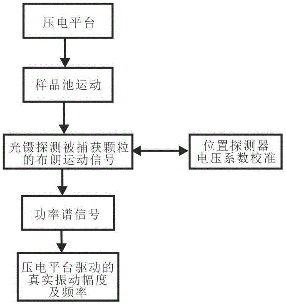
[0024] The detection process of the present invention is shown in figure 1 , use the piezoelectric platform to drive the movement of the sample chamber, use optical tweezers to detect the limited Brownian motion of the trapped particles, calibrate the voltage proportional coefficient of the position detector according to the hydrodynamic method, and in turn use the calibrated proportional coefficient to analyze the piezoelectric platform driven Constrain the power spectrum of the particle motion signal to obtain the true motion amplitude.

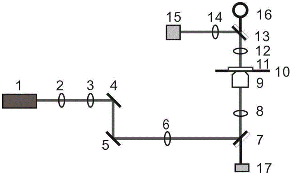
[0025] The basis of the present invention needs to set up a set of optical tweezers system with photoelectric detection, see figure 2 . The light beam emitted by t...


PUM


Abstract

The invention provides an optical trapping based method for in-situ calibration of displacement of a piezoelectric platform. High-precision detection of motion displacement amplitude and frequency of the piezoelectric platform can be realized by analysis of position signals of Brownian motion of standard-size globules trapped in an optical trap system. Besides detection of the piezoelectric platform, standard particles are trapped by laser under microscopic imaging, and position motion signals of the particles are quickly detected by a detector. The piezoelectric platform sends low-frequency fixed-amplitude motion signals to drive a sample chamber to move, the particles trapped in a light trap is subjected to actions of fluid periodic viscous resistance, and voltage proportionality coefficient of a position sensitive detector can be calibrated by detecting the motion signals of the particles. The piezoelectric platform sends signals to drive the sampling chamber to move again, a power spectrum of the trapped particles is analyzed, a peak of the power spectrum is compared with background thermal noise to invert real motion displacement amplitude of the piezoelectric platform, and frequency of the peak stands for motion frequency of the piezoelectric platform.

Description

technical field [0001] The invention belongs to the technical field of optical high-precision displacement detection and optical micro-manipulation, and in particular relates to a method for in-situ calibrating displacement of a piezoelectric platform based on optical capture. Background technique [0002] Piezoelectric stages are widely used in instruments that require precise control of displacement, such as biological microscopes, optical tweezers, and atomic force microscopes. The piezoelectric platform has the precision of nanometer movement, but in actual use, due to the influence of various factors such as the environment and fixed coupling parts, the movement amplitude of the fixed parts or samples carried by the drive will deviate from the nominal value of the instrument drive. It will lead to larger errors when the piezoelectric platform is used as an accurate measuring instrument to calibrate other signals. For optical tweezers and atomic force microscope systems...

Claims


Application Information

Patent Timeline
Patent Type & Authority Applications(China)
IPC IPC(8): G01B11/02
Inventor 周金华李迪李银妹钟敏成王自强
Owner UNIV OF SCI & TECH OF CHINA
Learn More