Experimental device for detecting aeroengine guider

An aero-engine and experimental device technology, applied in the direction of engine testing, measuring devices, jet engine testing, etc., can solve the problems affecting the authenticity and accuracy of test data, cumbersome operation, time-consuming and labor-intensive, etc., and achieve high test efficiency and easy operation Simple, easy-to-use effects

Active Publication Date: 2015-03-11
AECC AERO SCI & TECH CO LTD
View PDF5 Cites 7 Cited by
  • Summary
  • Abstract
  • Description
  • Claims
  • Application Information

AI Technical Summary

Problems solved by technology

At present, the device used for the air flow experiment of the aero-engine deflector is usually assembled with airflow valve, pressure gauge, pipe, temperature sensor, switch, seal, special process equipment and other components. During the experiment, it is required to record the instantaneous Parameters such as temperature and pressure require the simultaneous operation of multiple operators to complete the experiment, which is cumbersome and time-consuming.
The existing air flow experimental device is poorly assembled, and the gas leakage is difficult to control, and the gas leakage and whether the test piece can be accurately positioned and clamped will affect the authenticity and accuracy of the test data

Method used


Image

  • Experimental device for detecting aeroengine guider
  • Experimental device for detecting aeroengine guider
  • Experimental device for detecting aeroengine guider

Examples


Embodiment 1

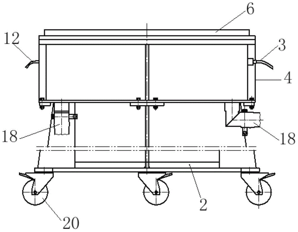
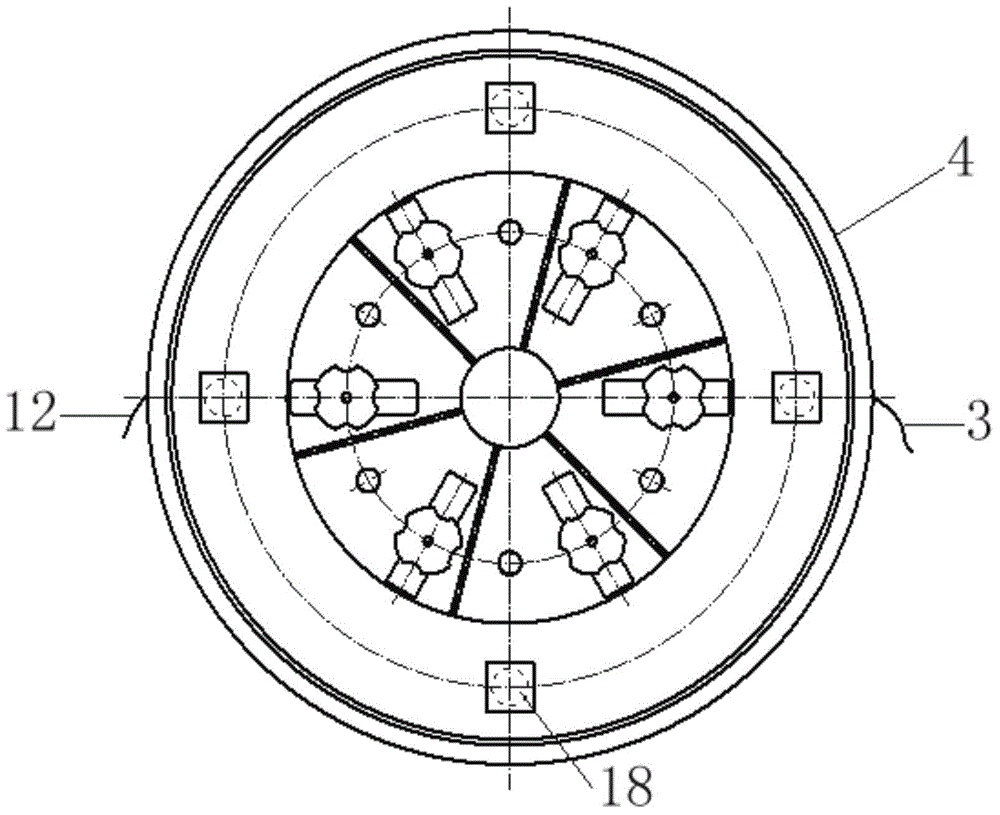
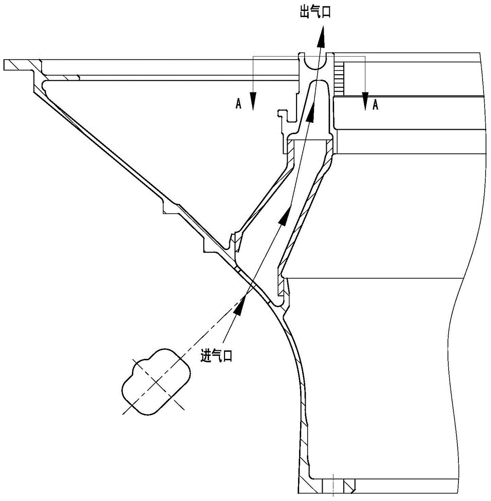
[0027] In this embodiment, the outline structure of the experimental device used to detect the aeroengine guide is as follows: Picture 1-1 and Figure 1-2 As shown, the local structure of the tested aero-engine guide is as follows diagram 2-1 and Figure 2-2 shown. The experimental device includes a device bracket 2, a cylinder chamber installed on the bracket for installing the guide 11 to be tested, a first annular chamber A located in the cylinder chamber, a second annular chamber B above the first annular chamber A, The sealing assembly used to measure the airtightness of the guider flow channel to be detected, the sealing assembly of the outlet of the sealing guider flow channel, the measuring airflow distribution device 1, the pressure sensor 3 and the temperature sensor 12 arranged on the second annular cavity B, and the pressure sensor 3 and the temperature sensor 12 arranged on the measuring airflow Flow sensor on the inlet duct of the dispensing unit.

[0028]Th...

Embodiment 2

[0030] In the present embodiment, adopt the experimental device of the present invention to carry out the air flow experiment on the guider of the aeroengine, put the guider 11 to be tested into the experimental device described in embodiment 1, and place the guider 11 small end flange to be tested 6 sets of pressing components 7 are airtightly compressed on the annular plate of the first annular chamber A, and the large end flange of the guide to be tested 11 is airtightly connected with the upper end of the outer cylinder through the coupling member 10, and the guide to be tested is guided by the sealing component. The outlet of the flow channel of the device 11 is sealed, and the sealing member 9 and the sealing member 13 are respectively arranged at the contact position between the guider 11 to be tested and the outer cylinder body 4 and the annular plate 15 (see Figure 3-1 ). Use a hose to connect the inlet pipe port and the air outlet pipe port, specifically, the connec...


PUM


Abstract

The invention discloses an experimental device for detecting an aeroengine guider. The experimental device comprises a device bracket, a barrel cavity which is formed in the bracket and used for mounting the guider to be detected, a first annular cavity A formed in the barrel cavity, a second annular cavity B formed above the first annular cavity A, a seal assembly for sealing the flow channel outlet of the guider, a measurement airflow distribution device, a pressure sensor and a temperature sensor which are arranged on the second annular cavity B, and a flow sensor arranged on an air inlet pipeline, wherein the barrel cavity comprises a barrel cavity bottom plate and an outer barrel body airtightly connected with the barrel cavity bottom plate; the first annular cavity A comprises an annular plate airtightly connected with the lower part of the outer barrel body and an inner barrel body airtightly connected with the barrel cavity bottom plate and the annular plate, a plurality of holes communicated with the second annular cavity B are formed in the annular plate, and an air inlet pipe hole is formed in the barrel cavity bottom plate forming the first annular cavity A; the second annular cavity B comprises the annular plate of the first annular cavity A, the outer barrel body and the outer wall surface of the guider to be detected.

Description

technical field [0001] The invention belongs to the field of detection of aero-engine guides, and in particular relates to an experimental device for detecting aero-engine guides. Background technique [0002] Aeroengine guides are an important part of aeroengines, and the flow channel area of ​​the guider is an important factor affecting engine performance. It is necessary to measure or detect the flow channel area of ​​the guider in the design and production of the guider. At present, the measurement of the flow channel area of ​​the aero-engine guider usually uses measuring tools and standard parts to measure the parameters such as the height and width of different sections of each flow channel, and calculates the flow channel area according to the measured parameters. However, the shape of the air flow channel of the aero-engine guide is complex, and it is necessary to use multiple sets of measuring tools and standard parts to complete the measurement. During the measure...

Claims


Application Information

Patent Timeline
Patent Type & Authority Applications(China)
IPC IPC(8): G01M15/02G01M15/14
Inventor 李芳黄梅赵小勇张强方海虹
Owner AECC AERO SCI & TECH CO LTD
Why Eureka
Try Eureka