A plane gap label

A slot and tag technology, applied in the field of planar slot tag antennas, can solve the problem of low gain and achieve the effect of long reading distance and wide bandwidth

Inactive Publication Date: 2015-03-11
BEIJING CEC HUADA ELECTRONIC DESIGN CO LTD
View PDF5 Cites 7 Cited by
  • Summary
  • Abstract
  • Description
  • Claims
  • Application Information

AI Technical Summary

Problems solved by technology

However, since the ordinary dipole antenna is placed on the surface of a higher dielectric constant object, the antenna frequency point must be guaranteed at 900MHz, the antenna size can only be small, and the gain is low.

Method used


Image

  • A plane gap label
  • A plane gap label
  • A plane gap label

Examples


Embodiment Construction

[0013] The specific implementation examples described here are only used to explain the present invention, not to limit the present invention.

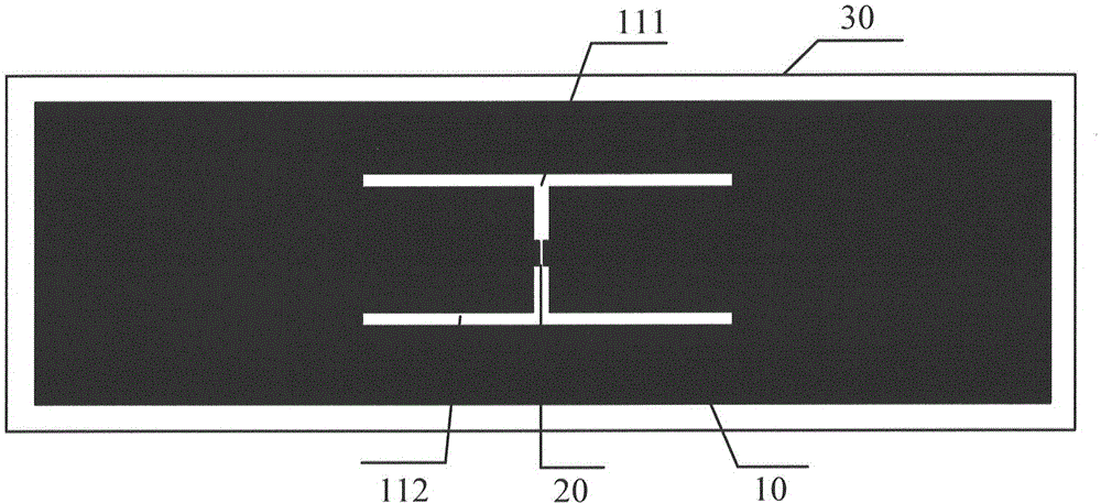
[0014] refer to figure 1 In this embodiment, the planar slot electronic tag includes an antenna 10 , a chip 20 and a substrate 30 . The substrate 30 is arranged in a rectangular shape for accommodating the antenna 10 and the chip 20 , wherein the antenna 10 matches the chip 20 . In this example, the plane gap electronic label is pasted on the high dielectric constant medium, the dielectric constant is 8-9, and the antenna of this example is simulated by HFSS simulation software.

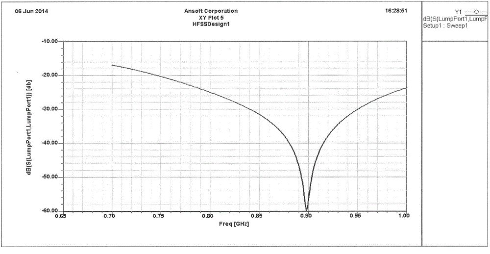
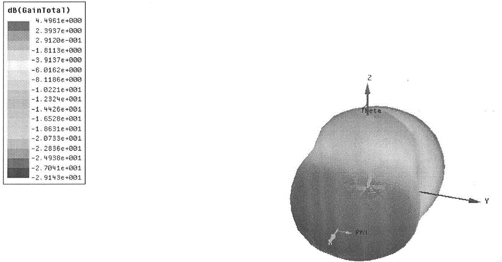
[0015] figure 2 For this embodiment tag antenna standing wave diagram, image 3 The three-dimensional gain diagram of the tag antenna in this example, Figure 4 The two-dimensional gain map of the tag antenna in this example shows that the gain is 0.2dBi directly above the tag.

[0016] In the above embodiments, the size of each part can be set accordin...


PUM


Abstract

The present invention discloses a plane gap label. The label includes an antenna, a chip and a substrate. The substrate is disposed in a rectangle shape and receives the antenna and the chip, wherein the antenna matches the chip. The antenna includes a rectangle radiant surface and a pair of T-shaped gaps. The pair of T-shaped gaps is located at the center of the substrate. The rectangle radiant surface includes a rectangle radiant surface with the pair of T-shaped gaps dug out. The pair of T-shaped gaps is disposed in a mirror image manner. The chip is located between the pair of T-shaped gaps. The plane gap label is applied to the surface of an object with a high dielectric constant, long in reading distance, wide in bandwidth, and good in applicability.

Description

Technical field: [0001] The invention relates to a planar slot tag antenna, which belongs to the technical field of microwave communication and is suitable for the field of radio frequency identification within the frequency range of 800MHz-1GHz. Background technique: [0002] The RFID system has obvious advantages in storing product information. The product information is stored in the electronic chip of the RFID tag, which can uniquely identify the identity of the product. RFID technology has gained considerable market share and is widely used in contactless payments. Moreover, the Internet of Things system is the development direction of the Internet of Things in the future, and RFID technology is an indispensable part of the Internet of Things system. In the ideal future, every object around us can be interconnected, positioned, and processed through the Internet, and RFID Technology is the foundation of it all. [0003] In many RFID applications, in many cases, RFID t...

Claims


Application Information

Patent Timeline
Patent Type & Authority Applications(China)
IPC IPC(8): G06K19/077
Inventor 许悦马纪丰赵军伟
Owner BEIJING CEC HUADA ELECTRONIC DESIGN CO LTD
Why Eureka
Try Eureka