Manufacture method of rigid substrate and flexible display

A flexible display and rigid substrate technology, which is applied in semiconductor/solid-state device manufacturing, semiconductor devices, electric solid-state devices, etc., can solve the problems of difficult control of stripping process conditions, complex stripping process, and damage to flexible substrates, and achieve simple stripping process Finish, simple glass craft, effect with obvious effect

Active Publication Date: 2015-03-11
CHENGDU VISTAR OPTEOLECTRONICS CO LTD
View PDF3 Cites 28 Cited by
  • Summary
  • Abstract
  • Description
  • Claims
  • Application Information

AI Technical Summary

Problems solved by technology

Although these two stripping methods have improved the stripping effect between the flexible substrate and the rigid substrate to a certain extent through continuous improvement of process conditions, the stripping process is complicated, the stripping of the amorphous silicon film and the germanium oxide film is not clean, and the flexible substrate is damaged. The problem still exists, and the process c

Method used


Image

  • Manufacture method of rigid substrate and flexible display
  • Manufacture method of rigid substrate and flexible display
  • Manufacture method of rigid substrate and flexible display

Examples


Embodiment 1

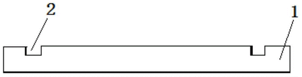
[0039] like figure 1 As shown, the present invention provides a rigid substrate for the manufacture of flexible displays. A groove 2 is formed on the rigid substrate 1 at the installation position of the flexible display, wherein the total area of ​​the groove 2 is the area of ​​the rigid substrate 1 10-50% of the rigid substrate 1, here the area occupied by the groove 2 can be made as small as possible, as long as the flexible display can be bonded and fixed.

Embodiment 2

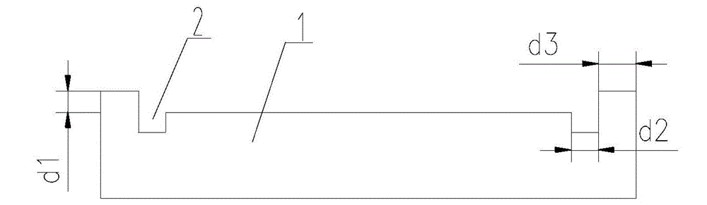
[0041] In order to protect the flexible display, the present invention forms a recessed area 3 for forming a flexible display on the plane of the rigid substrate 1, and the raised part of the rigid substrate 1 relative to the recessed area 3 is used for the clamping of the transmission mechanism in the subsequent manufacturing process. region, to prevent the edge of the flexible substrate 5 from being pinched, and to maximize the use of the flexible substrate. A first groove 21 is formed in the recessed area 3 , which is end-to-end closed, disposed in the recessed area 3 , and placed at the edge of the installation area of ​​the flexible display. like figure 2 and Image 6 structure shown.

[0042] Make a glass substrate with multiple grooves 2 as a rigid support substrate for a flexible display, wherein the rigid substrate 1 can be obtained by etching glass or other substrates, wherein d1 is equal to the thickness of the flexible substrate 5 and is 5-200 μm, and d2 is The...

Embodiment 3

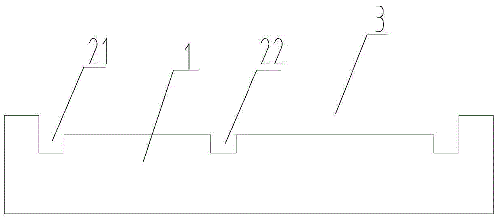
[0044] In order to enhance the bonding ability of the rigid substrate to the flexible display, another type of groove 2 is provided in the recessed area 3, that is, a linear second groove 22, wherein the linear second groove 22 can be a plurality of Distributed in a straight line, it is located in the middle of the installation area of ​​the flexible display. like image 3 and Figure 7 shown.

[0045] Wherein the groove width of the second groove structure 22 is 10mm˜100mm.


PUM

PropertyMeasurementUnit
Edge widthaaaaaaaaaa
Widthaaaaaaaaaa
Thicknessaaaaaaaaaa

Abstract

The invention discloses a manufacture method of a rigid substrate and a flexible display. A groove is formed in a region where the flexible display is formed on the rigid substrate, and the total area of the groove in the surface where the flexible display is formed on the rigid substrate is 10-50 percent of the surface area of the rigid substrate. According to the method, the groove is formed in the rigid substrate, by loading an adhesion agent in the groove, the adhesion between the groove position and a flexible substrate in the flexible display is realized, the adhesion area between the groove and the flexible substrate can be set according to the adhesion force, the more is the adhesion area, the higher the adhesion force between the groove and the flexible substrate is, as the area of the groove coated with the adhesion agent is controllable, the adhesion force between the groove and the flexible substrate is controllable, the use amount of the adhesion agent can be reduced and can be minimized, then the purpose that the groove and the flexible substrate are adhered to each other can be achieved, and as the area of the used adhesion agent is relatively small and the glass substrate adopts a structure easy to peel, the peeling technology can be simply accomplished.

Description

technical field [0001] The invention relates to the field of display technology, in particular to a method for manufacturing a rigid substrate and a flexible display. Background technique [0002] Flexible displays are displays based on flexible organic materials that can be rolled, folded, and even used as part of wearable computers, and have a very wide range of applications. Traditional flexible displays mainly use flexible substrates with a thickness of less than 100 microns, such as ultra-thin glass, stainless steel films, and plastic substrates. Due to the problems of fragility, wrinkling and deformation of the flexible substrate, in the actual production process, the flexible substrate is generally attached to the rigid substrate to complete the thin film transistor array production, OLED production and packaging processes, and finally, through the appropriate The lift-off method lifts off the rigid substrate to complete the fabrication of the flexible display. Ther...

Claims


Application Information

Patent Timeline
IPC IPC(8): H01L21/683H01L51/56
CPCH10K50/80H10K71/00
Inventor 胡明
Owner CHENGDU VISTAR OPTEOLECTRONICS CO LTD
Why Eureka
Try Eureka