Charge pump ripple rejection technology based on multistep discharge of flying capacitor

A kind of ripple suppression, flying capacitor technology, applied in electrical components, output power conversion devices, conversion equipment without intermediate conversion to AC, etc., can solve problems such as low efficiency and low overall efficiency

Inactive Publication Date: 2015-03-11
NANJING UNIV OF AERONAUTICS & ASTRONAUTICS
View PDF2 Cites 12 Cited by
  • Summary
  • Abstract
  • Description
  • Claims
  • Application Information

AI Technical Summary

Problems solved by technology

Since this scheme uses a low-efficiency linear regulated source

Method used


Image

  • Charge pump ripple rejection technology based on multistep discharge of flying capacitor
  • Charge pump ripple rejection technology based on multistep discharge of flying capacitor
  • Charge pump ripple rejection technology based on multistep discharge of flying capacitor

Examples


Embodiment Construction

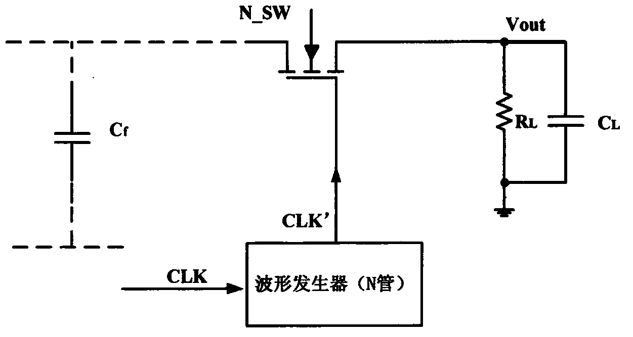
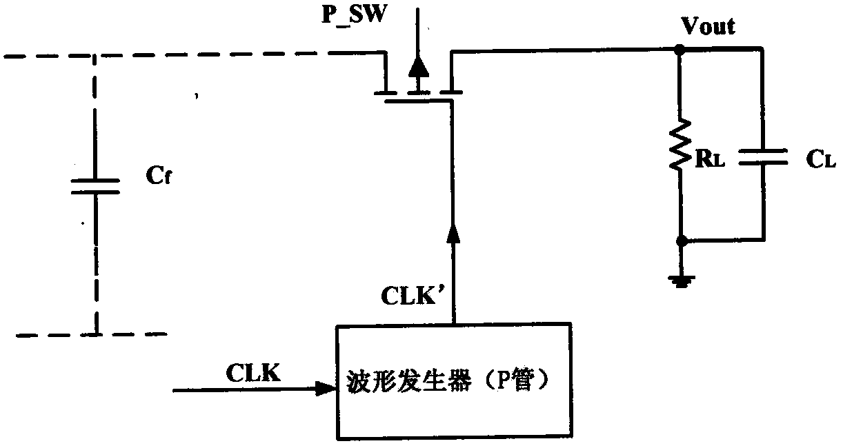
[0016] 1) The switching power tube connected to the output terminal is driven by the waveform generating circuit, and the flying capacitor discharges the load through the switch after a charging cycle, as shown in the appendix. figure 2 and attached image 3 shown;

[0017] 2) During the discharge cycle, the charge on the flying capacitor is not discharged once after the switch is closed, but is completed after n discharge states (n is an integer greater than 1);

[0018] 3) Each discharge state corresponds to the closing and opening process of a switch;

[0019] 4) The slopes of the rising edge and falling edge of the waveform driving the switch to close are separately controlled finely, as shown in the appendix. Figure 4 and attached Figure 5 shown;

[0020] 5) The leading edge of the waveform driving the gate of the switch tube (the rising edge for the N-type switch and the falling edge for the P-type switch) consists of two polylines with different slopes, of which ...


PUM


Abstract

The invention discloses a charge pump ripple rejection technology based on multistep discharge of a flying capacitor. As for a charge pump type DC (direct current)-DC convertor, load discharge is finished in multiple steps after the flying capacitor is charged once, so that discharge current is broken up into multiple small pulses from one large pulse. Meanwhile, the slopes of rising edge and falling edge of a waveform of a switching tube grid in drive connection with the flying capacitor and load, are controlled, so that a switch is connected and disconnected slowly, then each discharge current pulse is smoothed, discharge current approximates load current, and charges accumulated on a load capacitor are reduced, so that output voltage ripples are reduced.

Description

Technical field: [0001] The patent of the present invention covers the principle of switched capacitor DC-DC converter and ripple suppression technology. Background technique: [0002] With the continuous development of integrated circuit technology, the emergence of a large number of portable mobile terminals, especially in recent years, the popularity of smart phones, tablet computers, GPS and other products, electronic systems have also put forward more requirements for power supply, such as: portable performance, low power consumption, stable output, high efficiency, etc., promote the development of portable electronic device power technology. Electronic systems usually cannot be powered directly by a battery or power adapter, but require a voltage modulator to convert the unstable DC voltage into a stable system power supply. At present, DC-DC converters are mainly divided into two categories: linear regulators and switching power supply modulators. Linear regulators ...

Claims


Application Information

Patent Timeline
IPC IPC(8): H02M1/14H02M3/07
CPCH02M1/14H02M3/07H02M3/072
Inventor 卜刚方芳
Owner NANJING UNIV OF AERONAUTICS & ASTRONAUTICS
Why Eureka
Try Eureka