

Device and method for producing continuous low-temperature large-section atmospheric pressure plasma plumes
An atmospheric pressure plasma and large cross-section technology, applied in the field of plasma, can solve the problems of small cross-section, low time duty cycle, and high plasma plume temperature, and achieve large cross-sectional area, high time duty cycle, and low gas temperature Effect
- Summary
- Abstract
- Description
- Claims
- Application Information
AI Technical Summary
Problems solved by technology
Method used
Image

Examples
Embodiment 1
[0037] Example 1, a device for generating a continuous low-temperature large-section atmospheric-pressure plasma plume.
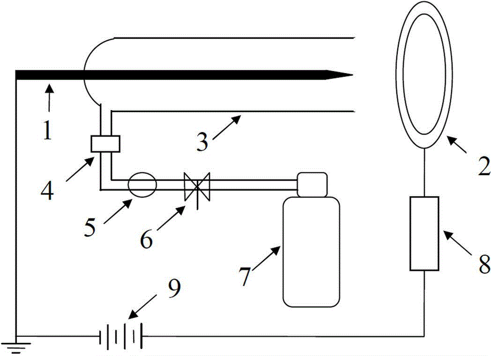
[0038] like figure 1 As shown, the device provided by the present invention includes a spray gun mechanism, an air supply mechanism and a power supply mechanism.
[0039] The spray gun mechanism includes a rod-shaped metal cathode 1 , a hollow closed anode 2 and a U-shaped dielectric tube 3 . One end of the rod-shaped metal cathode 1 is grounded, and the other end is a free end. The U-shaped medium pipe 3 has a sealed end and an open end; the U-shaped medium pipe 3 is placed laterally so that the sealed end and the open end are in the same horizontal plane. The free end of the rod-shaped metal cathode 1 penetrates into the U-shaped dielectric tube 3 from the bottom of the sealed end of the U-shaped dielectric tube 3, and extends to the open end of the U-shaped dielectric tube 3. The free end of the rod-shaped metal cathode 1 is connected to the U-shaped d...
Embodiment 2
[0046] Embodiment 2, a method for generating a continuous low-temperature large-section atmospheric pressure plasma plume.
[0047] The method for producing a continuous low-temperature large-section atmospheric pressure plasma plume provided by the present invention comprises the following steps:
[0048] a. Set up the spray gun mechanism.
[0049] like figure 1 As shown, the spray gun mechanism includes a rod-shaped metal cathode 1 , a hollow closed anode 2 and a U-shaped dielectric tube 3 . One end of the rod-shaped metal cathode 1 is grounded, and the other end is a free end. The U-shaped medium pipe 3 has a sealed end and an open end; the U-shaped medium pipe 3 is placed laterally so that the sealed end and the open end are in the same horizontal plane. The free end of the rod-shaped metal cathode 1 penetrates into the U-shaped dielectric tube 3 from the bottom of the sealed end of the U-shaped dielectric tube 3, and extends to the open end of the U-shaped dielectric t...
PUM
 Abstract
Description
Claims
Application Information