Method for detecting leaks in a brake pressure line, under braking pressure, of a rail vehicle

A brake pressure and leakage detection technology, which is applied in the direction of railway vehicle testing, brakes, brake components, etc., can solve the problems of unrecognized leakage, leakage, and increased identification of brake pressure loss.

Active Publication Date: 2015-03-11
KNORR BREMSE SYST FUR SCHIENENFAHRZEUGE GMBH
View PDF7 Cites 16 Cited by
  • Summary
  • Abstract
  • Description
  • Claims
  • Application Information

AI Technical Summary

Problems solved by technology

But due to such a construction, even larger leaks in the brake pressure pipes leading to the brake pressure are not recognized
The reason for this can lie in the supply capacity of the unit pressure converter (EDU), which supplies compressed air into the brake pressure pipe in the event of a leak, but thus increases the difficulty of identifying a loss o

Method used


Image

  • Method for detecting leaks in a brake pressure line, under braking pressure, of a rail vehicle

Examples


Embodiment Construction

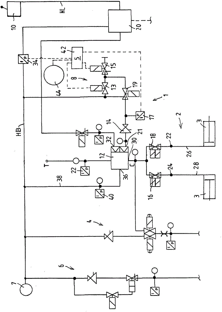
[0038]The drawing shows a circuit diagram of a part of a preferred embodiment of an electro-pneumatic compressed-air brake system 1 for a rail vehicle or a train consisting of a plurality of rail vehicles, the electro-pneumatic compressed-air brake system comprising Direct-acting electro-pneumatic microprocessor-controlled brakes ("direct brakes") and indirect-acting brakes ("indirect brakes").

[0039] A single rail vehicle has, for example, two bogies, and the bogies 2 have, for example, two braked axles, which each have two pneumatically actuated brake cylinders 3 . Only one brake cylinder 3 is depicted in each case in the figures. Each bogie 2 is controlled individually, for example by means of a compact control module CCM not explicitly shown here, so that for each bogie 2 a separate brake pressure C can be formed for, for example, four brake cylinders. For this purpose, an electronic brake controller 5 is integrated in each compact control module CCM. At a higher level...


PUM


Abstract

The invention relates to a method for detecting leaks in at least one brake pressure line (26, 28), under braking pressure (C), of a compressed air brake device (1) of a rail vehicle comprising an indirect electro-pneumatic brake, wherein the indirect electro-pneumatic brake has a master air vessel line (HB) to hold a master air vessel line pressure, and a compressed air source (7) supplying the master air vessel line (HB) with compressed air and is controlled by the master air line pressure in a master air line (HL), wherein the at least one brake pressure line (26, 28) under braking pressure (C) extends between a valve device (12), which controls the braking pressure (C) in dependence upon the master air line pressure in the master air line (HL), and at least one brake actuator (3), and wherein the method comprises a braking test carried out when the rail vehicle is stationary, having at least the following steps: a) checking whether, in the event of replenishment of compressed air from the compressed air source (7) into the master air vessel line (HB) being cut off, the master air vessel line pressure exceeds a preset limit value; and if so, b) controlling the master air line pressure in the master air line (HL) to apply the at least one brake actuator (3). According to the invention, within the framework of the braking test, the following further steps are carried out: c) monitoring the master air vessel line pressure to see whether c1) the value of the master air vessel line pressure arising after application of the at least one brake actuator (3) deviates by more than a preset difference from a preset plausible value for the master air vessel line pressure, and/or c2) in the period between the beginning and the end of the application of the at least one brake actuator (3), the pressure gradient of the master air vessel line pressure exceeds a preset pressure gradient; and d) if c1) and/or c2) applies, generating an error message that there is a leak in the at least one brake pressure line (26, 28).

Description

technical field [0001] The invention relates to a method according to the preamble of claim 1 for detecting leaks in a brake pressure line carrying the brake pressure of a compressed air brake system of a rail vehicle, which compressed air brake system With indirect electro-pneumatic brake. Background technique [0002] In known electro-pneumatic brakes, the brake pressure of each bogie, which usually has two braked axles, and each axle has two or more compressed air operated brake cylinder, the pressure sensor is arranged downstream of the unit pressure converter (EDU) configured as a relay valve. Due to such a design, however, even relatively large leaks in the brake pressure line carrying the brake pressure are not detected. The reason for this may lie in the supply capacity of the unit pressure converter (EDU), which supplies compressed air into the brake pressure line in the event of a leak, but this increases the difficulty of detecting a loss of brake pressure. Thi...

Claims


Application Information

Patent Timeline
IPC IPC(8): B60T17/22G01M3/26
CPCG01L5/28B60T17/228G01M3/26G01M17/08B60T13/365B60T13/683B60T13/741B60T17/04B60Y2400/306B60T8/3235B60T17/221G01M3/28
Inventor A·库尔B·明内奇克尔D·福伊希特
Owner KNORR BREMSE SYST FUR SCHIENENFAHRZEUGE GMBH
Why Eureka
Try Eureka