Ultrasonic imaging method and ultrasonic imaging device for realizing high-sensitivity imaging

An ultrasonic imaging method and high-sensitivity technology, applied in ultrasonic/sonic/infrasonic equipment control, ultrasonic/sonic/infrasonic diagnosis, ultrasonic/sonic/infrasonic Permian technology, etc., can solve complexity, failure, image The quality is good and bad and cannot be predicted in advance, so as to achieve high imaging sensitivity, avoid exceeding the limit, and improve the effect of sensitivity

Active Publication Date: 2015-03-18
SHENZHEN MINDRAY BIO MEDICAL ELECTRONICS CO LTD +1
View PDF4 Cites 4 Cited by
  • Summary
  • Abstract
  • Description
  • Claims
  • Application Information

AI Technical Summary

Problems solved by technology

However, although the temperature sensor can effectively detect and control the surface temperature of the probe, there are the following problems: on the one hand, the image quality can not be predicted in advance, which will affect the diagnosis doctor's expectation of the probe image; Installing a temperature sensor virtually increases the cost, complexity and probability of failure of the probe

Method used


Image

  • Ultrasonic imaging method and ultrasonic imaging device for realizing high-sensitivity imaging
  • Ultrasonic imaging method and ultrasonic imaging device for realizing high-sensitivity imaging
  • Ultrasonic imaging method and ultrasonic imaging device for realizing high-sensitivity imaging

Examples


Embodiment 1

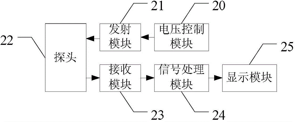
[0039] This embodiment provides an ultrasonic imaging device, such as figure 2 As shown, it includes: a voltage control module 20 , a transmitting module 21 , an ultrasonic probe 22 , a receiving module 23 , a signal processing module 24 and a display module 25 . The system controls the shape of the transmission pulse and the array elements involved in the transmission, respectively controls the transmission voltage of each imaging mode through the voltage control module 20, and the ultrasonic probe 22 converts the excited electrical signal into an acoustic signal, and transmits it to the object to be detected (for example, human tissue ). The ultrasonic echo reflected by the object to be detected is received by each element of the ultrasonic probe and converted into an electrical signal to form an ultrasonic echo signal (ultrasonic echo signal). The receiving module 23 receives these ultrasonic echo signals (ultrasonic echo signals) and performs corresponding processing, an...

Embodiment 2

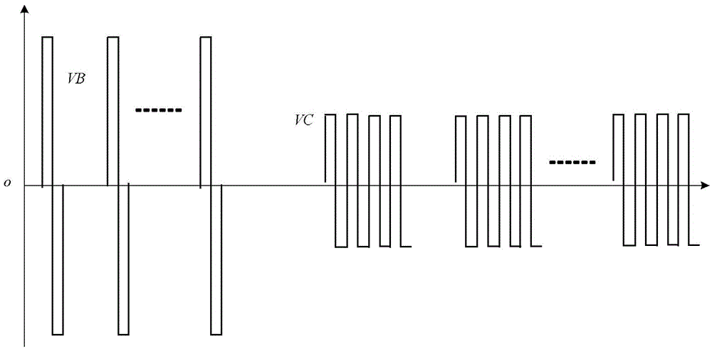
[0067] The difference between this embodiment and Embodiment 1 lies in the restriction on the increased second-mode pulse emission voltage (ie, the aforementioned second mode second voltage) in the high-sensitivity imaging step. At this time, the specific scanning process involved in the emission module or the emission step of this embodiment is as follows: Image 6 As shown, under the normal imaging step, the working voltage of the second mode scan is relatively small. When the high-sensitivity imaging step is triggered, the emission voltage VC of the second mode scan is instantly increased to the maximum limit of MI stipulated by the FDA, which meets the requirements of medical ultrasound. The output index standard, and the emission voltage VB of the first mode scan is correspondingly reduced. After the high-sensitivity imaging step continues to work for the first preset time t1, it will automatically switch to the normal imaging step, and the normal imaging step will continu...

Embodiment 3

[0069] Based on Embodiment 1, in this embodiment, after switching from the high-sensitivity imaging step back to the normal imaging step, the normal imaging step continues to work for a period of time (such as the second preset time t2), and the second preset time is greater than or equal to the preset failure time. When implemented, t1 and t2 are limited to: after the ultrasonic imaging device switches back and forth between the high-sensitivity imaging step and the normal imaging step for several (t1+t2) hours, the surface temperature rise of the ultrasonic probe meets the requirements on the probe surface temperature rise in medical ultrasound. Restricted standards. Therefore, it can be ensured that the ultrasonic imaging device will not continue to work at higher emission energy, and finally ensure that the temperature rise of the probe surface will not exceed the requirements of IEC regulations during all working hours.

[0070] IEC stipulates that in any case, the tempe...


PUM


Abstract

An ultrasonic imaging method and an ultrasonic imaging device which realize high-sensitivity imaging. The ultrasonic imaging method comprises: in a normal imaging step, conducting combined scanning several times on an object to be detected, each combined scanning comprising first mode scanning and second mode scanning; and entering a high-sensitivity imaging step, where a transmission voltage of a second mode pulse is adjusted to be higher than a transmission voltage of the second mode pulse in the normal imaging step, and a transmission voltage of a first mode pulse is adjusted to be lower than a transmission voltage of the first mode pulse in the normal imaging step. By way of adding a high-sensitivity imaging step, the ultrasonic imaging method improves a transmission voltage of a second mode pulse and reduces a transmission voltage of a first mode pulse, so that the sensitivity of imaging can be improved.

Description

technical field [0001] The invention relates to the field of ultrasonic imaging, in particular to an ultrasonic imaging method for realizing high-sensitivity imaging and an ultrasonic imaging device. Background technique [0002] Medical ultrasonic imaging equipment uses the propagation of ultrasonic waves in the human body to obtain ultrasonic characteristic information of human tissue and organ structures. Ultrasonic imaging equipment usually uses multi-element probes. High-voltage pulse waves are loaded on each array element of the probe, which excites the array elements to generate high-frequency ultrasonic waves and then forms a transmission beam to enter the human body. Each array element of the probe receives echoes scattered or reflected by human tissue structures. , form the receiving beam, and the ultrasonic imaging equipment extracts the information in the ultrasonic echo, and forms various imaging modes for display. Different types of imaging modes correspond to...

Claims


Application Information

Patent Timeline
Patent Type & Authority Applications(China)
IPC IPC(8): A61B8/06
CPCA61B8/00A61B8/14A61B8/54A61B8/48A61B8/5207G01S7/5202G01S15/8979A61B8/06
Inventor 李雷杨鹏飞
Owner SHENZHEN MINDRAY BIO MEDICAL ELECTRONICS CO LTD
Why Eureka
Try Eureka