Method for controlling charging of a hybrid or electric vehicle

A technology of electric vehicles and vehicles, which is applied in the direction of electric vehicle charging technology, electric vehicles, air flow to electric energy conversion, etc., and can solve problems such as limiting the availability of vehicles

Active Publication Date: 2015-03-18
VOLVO CAR CORP
View PDF6 Cites 15 Cited by
  • Summary
  • Abstract
  • Description
  • Claims
  • Application Information

AI Technical Summary

Problems solved by technology

[0005] However, such systems limit the availability of the vehicle to the user during charging, for example

Method used


Image

  • Method for controlling charging of a hybrid or electric vehicle
  • Method for controlling charging of a hybrid or electric vehicle
  • Method for controlling charging of a hybrid or electric vehicle

Examples


Embodiment Construction

[0031] In the following description, the invention will be described primarily with reference to a method for securing and locking a charging cable to a hybrid or electric vehicle. In said description, the control unit is located inside the vehicle. However, the control unit may be located elsewhere, eg in the charging station.

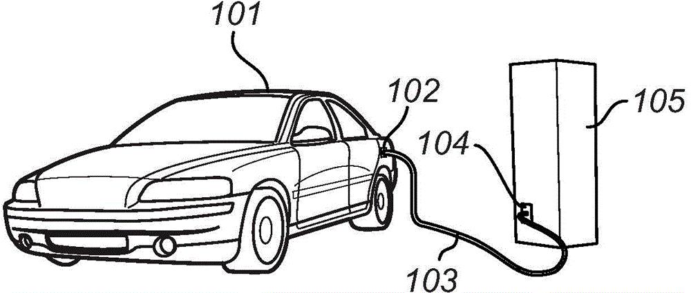
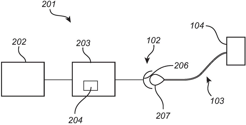
[0032] figure 1 An exemplary application of the invention is shown. exist figure 1 , the electric vehicle 101 is connected to an external power source 104 via a charging cable 103 at a power inlet 102 of the electric vehicle 101 . For example, external power source 104 may be located at electric vehicle charging station 105 or it may be connected to a conventional household electrical outlet. The invention is power source independent, so the power provided may be, for example, 220V, 50Hz or 110V, 60Hz via a single-phase output or a three-phase output. The charging cable 103 may be a conventional wire, which may or may not include any other compon...


PUM


Abstract

According to the invention there is provided a method and a system for controlling a lock state of a charging cable (103) connected to a power inlet (102) of an electrical vehicle (101), the vehicle (101) comprising an energy storage device (202) electrically connected to the power inlet (102), a lock unit (206) for locking the charging cable (103) to the power inlet (102), and a control unit for controlling a lock state of the lock unit (206).

Description

technical field [0001] The invention relates to the connection between a power source and an electric vehicle or a hybrid vehicle. In particular, the invention relates to the working state of such connections. Background technique [0002] Electric and hybrid vehicles have recently become more and more commonplace on roads around the world. One thing they all have in common is that they all require powerful rechargeable batteries. Regardless of the size of such batteries installed in, for example, electric vehicles, they essentially have to be charged on a daily basis, depending on how often and how far the vehicle is driven. In a hybrid vehicle, the battery can be charged directly by the internal combustion engine, or it can be charged by an external power source, for example, in a plug-in hybrid vehicle. [0003] The power from the power source required to charge the rechargeable battery of an electric vehicle is considerable. Due to the high power, the cables and conn...

Claims


Application Information

Patent Timeline
Patent Type & Authority Applications(China)
IPC IPC(8): B60L11/18
CPCB60L8/006G07C2209/08B61C3/00B60L11/1879B60L11/1818B60L11/1812B60L11/1838H01R13/639B60L11/1877Y02T10/7072Y02T90/14B60L2210/30B60L2240/36B60L2240/80B60L2270/32B60L2270/34Y02T10/70Y02T10/72B60L53/16B60L3/00B60L53/68Y04S30/12Y02T90/12Y02T90/16Y02T90/167B60L53/22B60L3/0069B60L50/52B60L53/18
Inventor A·赫肯斯特伦P·托尔斯滕松M·哈达尔查
Owner VOLVO CAR CORP
Why Eureka
Try Eureka