
Corrosion resistant method and structure of steel column base with shoe plate

A shoe plate and steel column technology, applied to building components, building insulation materials, etc., can solve problems such as easy accumulation of water or corrosive liquid, reduced structural durability, and easy corrosion of steel column feet, etc., to achieve simple and convenient force transmission path, Solve the effect of easy corrosion and convenient construction

Inactive Publication Date: 2015-03-18
GUIYANG AL-MG DESIGN & RES INST
View PDF5 Cites 2 Cited by
  • Summary
  • Abstract
  • Description
  • Claims
  • Application Information

AI Technical Summary

Problems solved by technology

The bottom of the existing rigid column foot is generally provided with a bottom plate, the top of the bottom plate is welded with I-beam, and the flange connecting the I-beam and the bottom plate is welded with a shoe plate, and a closed space is formed between the shoe plate and the bottom plate. It is easy to accumulate water or corrosive liquid inside, and it is not easy to clean
Because the closed space is in contact with water or corrosive liquid for a long time, the steel column foot is easy to corrode, which reduces the durability of the structure and limits the application of the exposed steel structure column foot with shoe plate in steel structure buildings
In order to prevent water or corrosive liquids from accumulating in the closed space at the base of the steel column foot, the current practice is to wrap the steel column limb with concrete with a height of not less than 150mm when the column foot is used below the ground, but the current practice limits Exposed use of steel structure column feet with shoe plates

Method used


Image

  • Corrosion resistant method and structure of steel column base with shoe plate

Examples


Embodiment Construction

[0015] The present invention will be further described in detail below in conjunction with the accompanying drawings, but not as any limitation to the present invention.

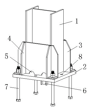
[0016] An anti-corrosion method for steel column feet with shoe plates, such as figure 1 shown. The method is to drill a set of drainage holes at the bottom of the shoe plate welded with the I-shaped steel wing plate and the bottom plate, so as to drain the accumulated water or corrosive liquid in the closed space at the foot of the steel column in time, so as to realize the steel column with shoe plate Antiseptic purpose for feet. The drain hole adopts a semicircular hole or a rectangular hole, and a gate shape is formed between the bottom surface of the hole and the bottom plate to expand the drain channel.

[0017] The steel column foot structure with shoe plate formed according to the aforementioned method includes a base plate 2, the top surface of the base plate 2 is welded to the bottom end o...


PUM


Abstract

The invention discloses a corrosion resistant method and a structure of a steel column base with a shoe plate. The method is to drill a set of drainage holes in the bottom of the shoe plate for welding a joist steel wing plate with a baseplate so as to timely drain water or corrosive liquid falling in a closed space of the steel column base to realize the corrosion resistant purpose of the steel column base with the shoe plate. Several drainage holes are drilled in the bottom of the shoe plate surrounding the closed space of the steel column base, are semicircular holes or rectangular holes, and tightly adhere to a bottom hole plane to timely drain the water or corrosive liquid entering the closed space of the steel column base so as to prevent the water or corrosive liquid in the closed space of the steel column base, so that the durability of the steel column base is improved, and the steel column base with the shoe plate can be exposed outside for use. The corrosion resistant method and structure have the characteristics of low cost, simple production, convenience for construction, simple force transfer path, strong bending resistance and shearing resistance and reliable connection with a foundation, effectively solve the problem of easy corrosion of a traditional exposed steel structural column base with the shoe plate, and improve the structural durability.

Description

technical field [0001] The invention relates to an anticorrosion method and structure of a steel column foot with a shoe plate, and belongs to the technical field of anticorrosion of rigid column feet. Background technique [0002] The exposed rigid column foot is a commonly used form of steel structure column foot. The bottom of the existing rigid column foot is generally provided with a bottom plate, the top of the bottom plate is welded with I-beam, and the flange connecting the I-beam and the bottom plate is welded with a shoe plate, and a closed space is formed between the shoe plate and the bottom plate. It is easy to accumulate water or corrosive liquid inside, and it is not easy to clean. Because the closed space is in contact with water or corrosive liquid for a long time, the steel column foot is easy to corrode, which reduces the durability of the structure and limits the application of the exposed steel structure column foot with shoe plate in steel structure bu...

Claims


Application Information

Patent Timeline
Patent Type & Authority Applications(China)
IPC IPC(8): E04B1/64
Inventor 王伟
Owner GUIYANG AL-MG DESIGN & RES INST
Learn More