

Carburetor
A technology for carburetors and air intake passages, applied to carburetors, machines/engines, engine components, etc., can solve problems such as difficulty in passing exhaust emission regulations, inability to perform fuel metering and supply correctly, and increased costs, so as to reduce power consumption low power consumption, simple structure, and improved output performance
- Summary
- Abstract
- Description
- Claims
- Application Information
AI Technical Summary
Problems solved by technology
Method used
Image

Examples
Embodiment Construction
[0028] Embodiments of the present invention will be described below based on the drawings.
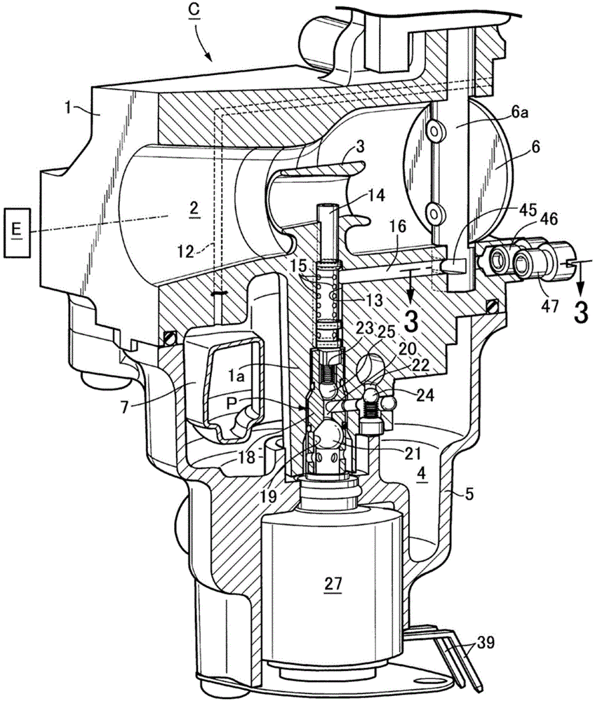
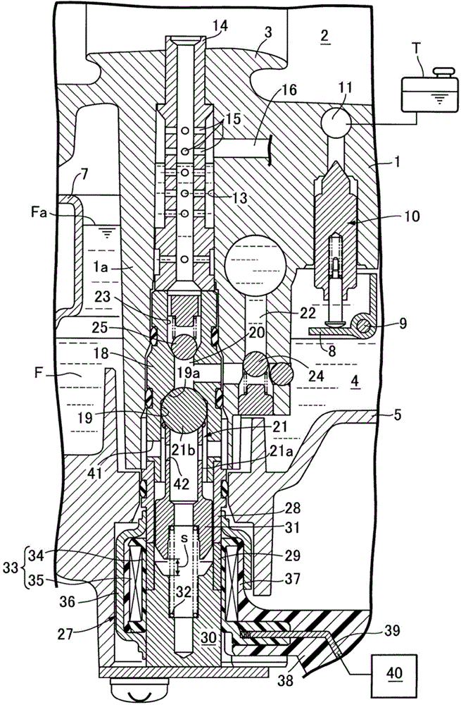
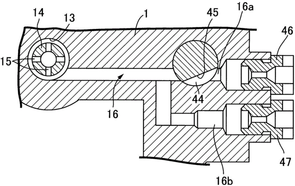
[0029] First, in figure 1 and figure 2 Among them, the carburetor C is used for a single-cylinder engine, or is provided for each cylinder of a multi-cylinder engine. The carburetor C includes a carburetor body 1 having a horizontal air intake passage 2 connected to the air intake port of the engine E, and a float room (float room) that is airtightly joined to the lower end surface of the carburetor body 1 and partitioned therebetween. 4 of the float chamber body 5. The float chamber body 5 is detachably fastened on the carburetor body 1 by bolts.
[0030] In the intake passage 2 , a Venturi tube 3 is disposed at the center thereof, and a butterfly valve-type throttle valve 6 is disposed upstream of the Venturi tube 3 .
[0031] The carburetor body 1 integrally has a fuel boss (boss) 1a protruding into the float chamber 4 from the central part of the lower surface thereof, and a f...
PUM
 Abstract
Description
Claims
Application Information