Heat exchanger arrangement and production method

A manufacturing method and technology of heat exchangers, applied to heat exchanger sealing devices, indirect heat exchangers, heat exchanger types, etc., can solve problems such as insufficient sealing quality, unacceptable cost, adverse effects on heat exchanger efficiency, etc.

Active Publication Date: 2015-03-18
MODINE MFG CO
View PDF7 Cites 2 Cited by
  • Summary
  • Abstract
  • Description
  • Claims
  • Application Information

AI Technical Summary

Problems solved by technology

[0004] It has been found that the quality of the seal is still not good enough
There is still always an uncooled air flow that flows in splits between the housing wall and the radiator block, thereby adversely affecting the efficiency of the heat exchanger
[0005] The filling of additional sealing material, as proposed in numerous other publications from the prior art, is not advisable from a cost perspective

Method used


Image

  • Heat exchanger arrangement and production method
  • Heat exchanger arrangement and production method
  • Heat exchanger arrangement and production method

Examples


Embodiment Construction

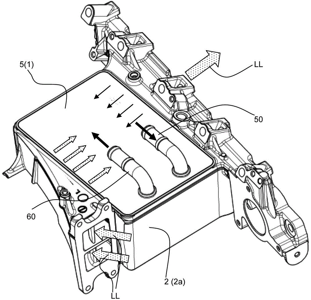
[0028] Such as figure 1 , 8 and 9, as an indirect charge air radiator in a motor vehicle for cooling the compressed charge air fed to an internal combustion engine. The heat exchanger arrangement can also be used for other purposes and also outside the field of motor vehicle applications.

[0029] exist Figures 1 to 3 An inlet 50 and an outlet 60 for the cooling liquid can be seen in , which are fastened to the top plate 5 which belongs to the radiator block 1 . from figure 1 In particular the external features of the housing 2 shown in the figure should be appreciated that there is an inlet for the charge air LL to be cooled on the housing 2 and an inlet for the already cooled charge air LL on the opposite side (not shown). Outlet for cooled charge air, the inlet and outlet are indicated by square arrows.

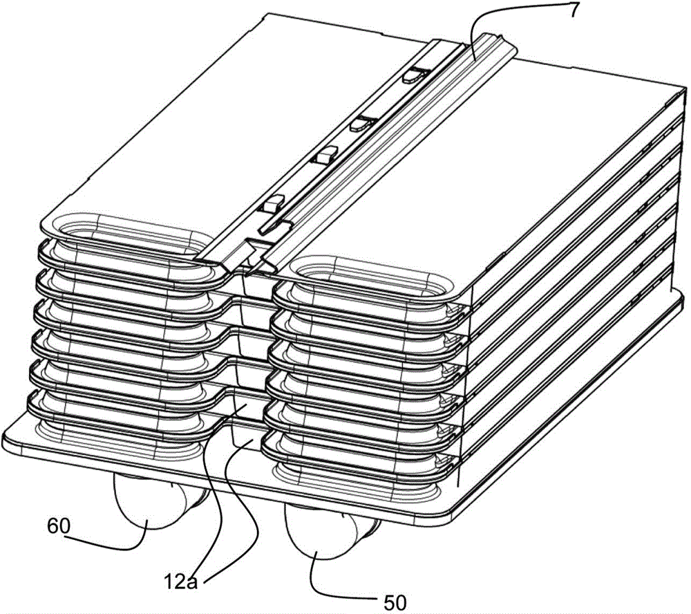
[0030] The radiator block has a flow path 10 for the cooling liquid, which is formed in the illustrated embodiment by a pair of plates P (consisting of plates 11A, 1...


PUM


Abstract

A heat exchanger arrangement, for example for an internal combustion engine, having a brazed radiator block (1) which has flow paths (10) formed from pairs of plates and has flow ducts (3) between the plate pairs (P), wherein in each case at least one plate (11) of each plate pair has a plate elongation (12), and wherein the brazed radiator block is arranged in a housing (2) and, at its circumference, is sealed off with respect to the housing. To improve the sealing action between the radiator block (1) and the housing (2), it is provided according to the invention that the plate elongations (12) are formed such that a prescribed dimension of the brazed radiator block (1) can be set by means of deformation of the plate elongations (12).

Description

technical field [0001] The invention relates to a heat exchanger arrangement, for example for an internal combustion engine, having a welded radiator block with a flow path through a mating plate consisting of plates and a mating A flow path is formed between the plates, wherein each plate of each mating plate has a plate extension, wherein the welded heat sink block is disposed in a housing and is sealed relative to the housing on its periphery. The invention also relates to a method of manufacturing a heat exchanger device. Background technique [0002] Such a heat exchanger is known from the previous patent application DE 10 2012 008 700.4. [0003] In this previous patent application, the protected plate extension has the task of blocking the charge air to be cooled from flowing through the flow channel in the region where it is installed and thereby deflecting the charge air to the radiator block. Central, where heat exchange can take place more efficiently. Said pla...

Claims


Application Information

Patent Timeline
Patent Type & Authority Applications(China)
IPC IPC(8): F28D9/00F28F3/00F28F11/02F28F21/08B23P15/26F02B29/04
CPCF28D1/0383F28D1/0358F28F3/06B21D53/04F02B29/0462F28F9/0075F28D9/0056F28D2021/0082F28F2230/00F28F2275/14Y10T29/49366Y02T10/12F28D1/0333F28D1/0341
Inventor R·格吕克
Owner MODINE MFG CO
Why Eureka
Try Eureka