Photomask and overlay-accuracy monitoring method of same

A technology for overlay accuracy and photomask, which is applied in the field of photomask and photomask overlay accuracy monitoring, can solve the problems of difficult process and inconvenient monitoring for photomask overlay accuracy monitoring, shortens the work cycle, The effect of simplifying work and good position accuracy

Inactive Publication Date: 2015-03-18
上海凸版光掩模有限公司
View PDF8 Cites 7 Cited by
  • Summary
  • Abstract
  • Description
  • Claims
  • Application Information

AI Technical Summary

Problems solved by technology

[0009] In view of the shortcomings of the prior art described above, the purpose of the present invention is to provide a photomask and a method for monitoring the overlay accuracy of the

Method used


Image

  • Photomask and overlay-accuracy monitoring method of same
  • Photomask and overlay-accuracy monitoring method of same
  • Photomask and overlay-accuracy monitoring method of same

Examples


Embodiment 1

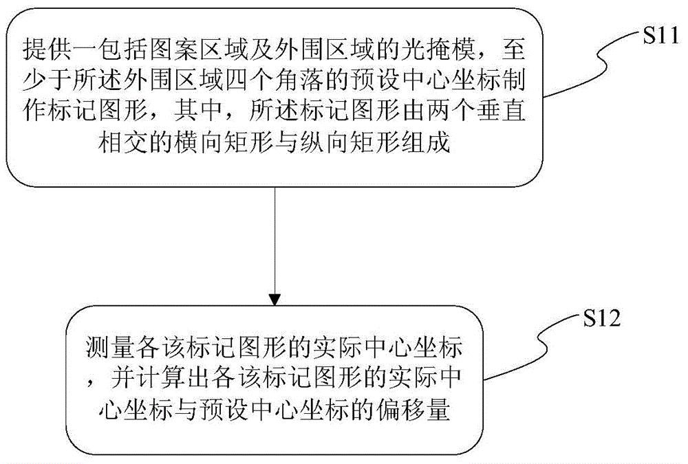
[0049] like Figure 1 ~ Figure 4 As shown, this embodiment provides a method for monitoring the overlay accuracy of a photomask, which at least includes the following steps:

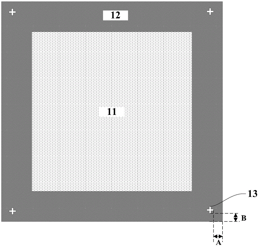
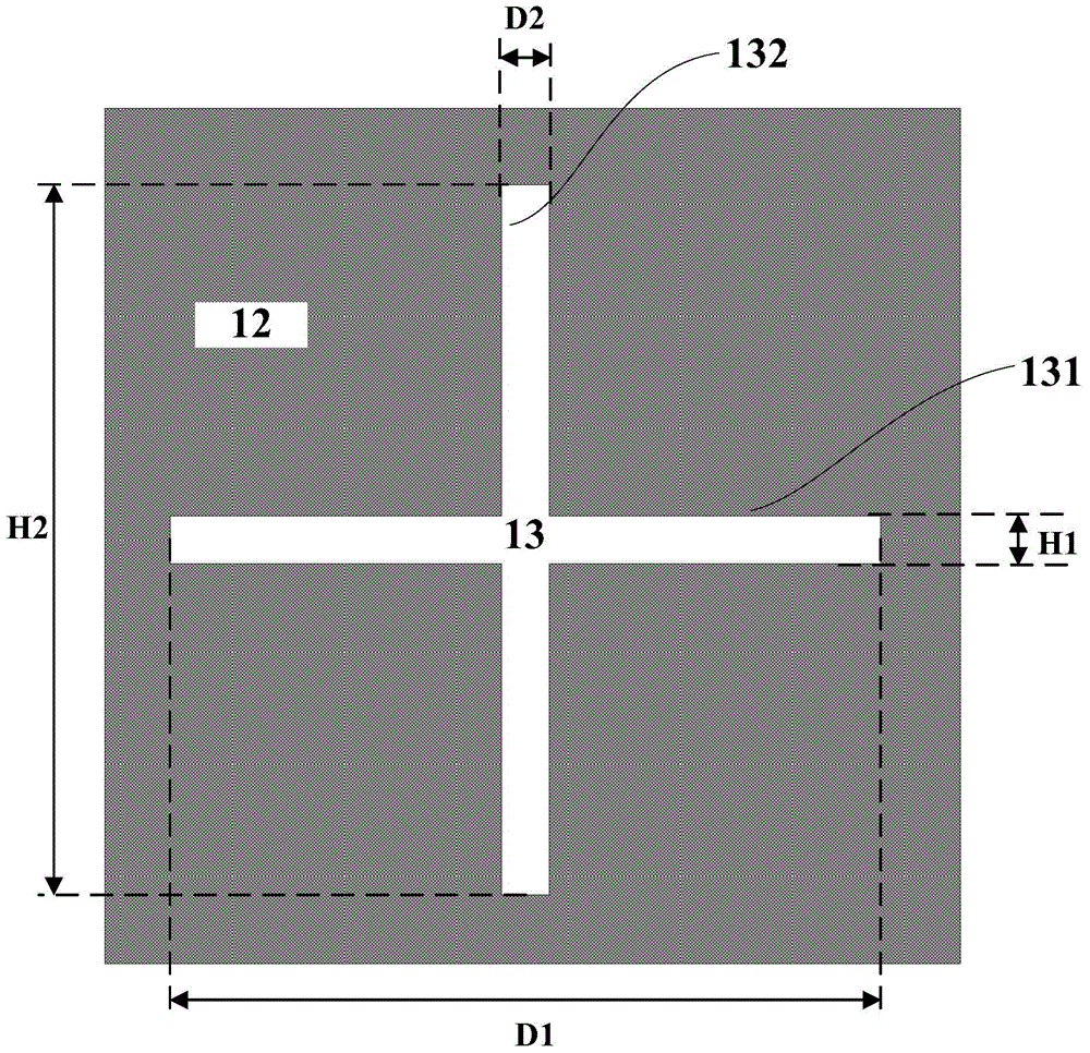
[0050] like Figure 1 ~ Figure 3 As shown, step 1) S11 is performed first, providing a photomask including a pattern area 11 and a peripheral area 12, at least at the preset central coordinates of the four corners of the peripheral area 12 to make a mark pattern 13, wherein the mark The graph 13 is composed of two vertically intersecting horizontal rectangles 131 and vertical rectangles 132 .

[0051]As an example, the photomask is composed of a light-transmitting layer and a light-shielding layer bonded to the surface of the light-transmitting layer. Specifically, the transparent layer is glass, and the light-shielding layer is chrome.

[0052] The graphic area 11 is used to make photolithographic patterns required by the photolithography process. The four corners of the peripheral region 12 are gener...

Embodiment 2

[0071] like figure 2 and image 3 As shown, the present embodiment provides a photomask, comprising:

[0072] Graphics area 11 and a peripheral area 12 surrounding said graphics area;

[0073] The four corners of the peripheral area 12 respectively have marking patterns 13 , and the marking patterns 13 are composed of vertically intersecting horizontal rectangles 131 and vertical rectangles 132 .

[0074] As an example, the photomask is composed of a light-transmitting layer and a light-shielding layer bonded to the surface of the light-transmitting layer. Specifically, the transparent layer is glass, and the light-shielding layer is chromium. The marking pattern 13 is a light-transmitting pattern formed by removing part of the light-shielding layer.

[0075] The graphic area 11 is used to make photolithographic patterns required by the photolithography process. The four corners of the peripheral region 12 are generally not used to make photolithographic patterns, and the ...


PUM

PropertyMeasurementUnit
Widthaaaaaaaaaa
Widthaaaaaaaaaa
Widthaaaaaaaaaa

Abstract

The invention provides a photomask and an overlay-accuracy monitoring method of the same. The monitoring method comprises the steps: 1) providing a photomask comprising a figure area and a peripheral area, and preparing graphic marks at the preset center coordinates of at least four corners of the peripheral area, wherein each graphic mark is composed of a transverse rectangle and a longitudinal rectangle which are perpendicularly crossed; and 2) measuring the actual center coordinates of the graphic marks, and calculating out the deviation of the actual center coordinate and the preset center coordinate of each graphic mark. The photomask and the monitoring method are capable of effectively improving the overlay-accuracy monitoring simplicity, reducing monitoring error probability and shortening working period. By putting the graphic marks at four corners of the photomask and far away from a photoetched main pattern, the position precision can be well monitored, and also any influence is caused on the photoetched main pattern. The monitoring method is simple and practicable in steps and is suitable for production monitoring.

Description

technical field [0001] The invention belongs to the field of semiconductor manufacturing, in particular to a photomask and a method for monitoring the engraving precision of the photomask. Background technique [0002] In the semiconductor process, photolithography is a crucial step. Through a series of steps such as photolithography alignment and exposure, the process of transferring the mask pattern to the wafer can be realized. Generally, in the process of forming a semiconductor chip, a multi-layer photolithography process is required to complete the entire manufacturing process. This makes the positional alignment of the current lithography pattern and the previous layer lithography pattern particularly important. The overlay accuracy refers to the positional alignment error of the wafer layer and the photolithography pattern of the layer. [0003] Photomasks have an index of positional accuracy. In the existing marking patterns for measuring the position accuracy of...

Claims


Application Information

Patent Timeline
IPC IPC(8): G03F1/44
CPCG03F1/44
Inventor 李晓梅
Owner 上海凸版光掩模有限公司
Why Eureka
Try Eureka