Overheating protection circuit, LED (light-emitting diode) drive circuit and lamp

An overheating protection circuit and LED driving technology, which is applied to the layout of electric lamp circuits, electric light sources, lighting devices, etc., can solve the problems of reduced service life of LED lamps, achieve long service life, and avoid the effects of light decay of light sources

Active Publication Date: 2015-03-18
SHENZHEN OCEANS KING LIGHTING ENG CO LTD +1
View PDF4 Cites 8 Cited by
  • Summary
  • Abstract
  • Description
  • Claims
  • Application Information

AI Technical Summary

Problems solved by technology

[0003] Based on this, it is necessary to provide an overheating protection circuit for reducing the service life of LED lamps due to excessive operating temperature.

Method used


Image

  • Overheating protection circuit, LED (light-emitting diode) drive circuit and lamp
  • Overheating protection circuit, LED (light-emitting diode) drive circuit and lamp
  • Overheating protection circuit, LED (light-emitting diode) drive circuit and lamp

Examples


Embodiment Construction

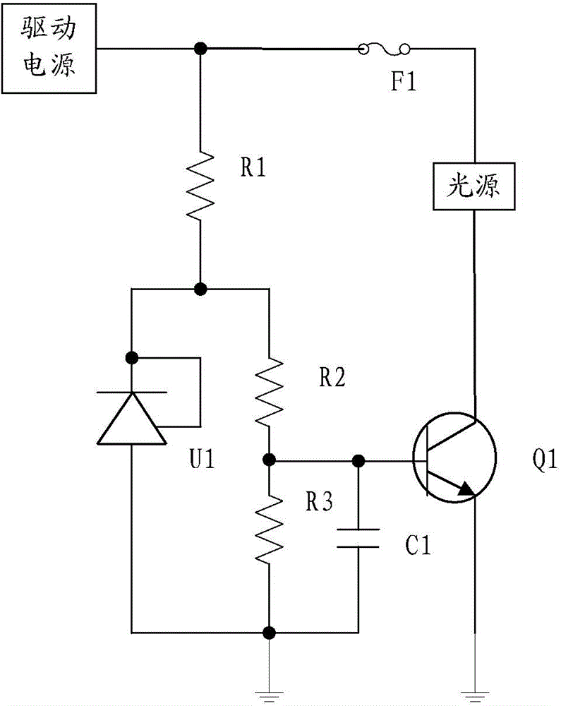
[0020] Such as figure 1 Shown is a schematic diagram of an overheating protection circuit of an embodiment. The overheat protection circuit is used to detect the temperature of the key points of the lamp and adjust the output current of the working circuit, including: a first resistor R1, a second resistor R2, a third resistor R3, a controllable precision voltage source U1, a first capacitor C1 and a second capacitor. A switching tube Q1. Wherein, the second resistor R2 is a positive temperature coefficient thermistor.

[0021] The second resistor R2 is connected in series with the third resistor R3 and then connected in parallel with the controllable precision voltage source U1, and finally connected to the external driving power supply through the first resistor R1, and one end of the third resistor R3 is grounded. The positive pole of the first capacitor C1 is connected to the common end of the second resistor R2 and the third resistor R3, and the negative pole of the fir...


PUM


Abstract

The invention relates to an overheating protection circuit, which is used for detecting the temperature of a key point of a lamp and regulating the output current of a working circuit, the overheating protection circuit comprises a first resistor, a second resistor, a third resistor, a controllable precision voltage source and a first switching transistor; the second resistor and the third resistor which are connected in series are connected in parallel with the controllable precision voltage source and then connected with an external driving power supply through the first resistor, and one end of the third resistor is grounded; the control end of the first switching transistor is connected with the common end of the second resistor and the third resistor, the high-potential end of the first switching transistor is connected with an LED (light-emitting diode) light source, and the low-potential end of the first switching transistor is grounded; the second resistor is a positive temperature coefficient thermistor. The invention also discloses an LED drive circuit and a lamp which apply the overheating protection circuit. By detecting the temperature of the lamp, the overheating protection circuit can automatically regulate the output current of the lamp, so that the heat produced by the lamp can be reduced. The service life of the lamp is long.

Description

technical field [0001] The invention relates to circuit protection, in particular to an overheating protection circuit, an LED driving circuit and a lamp. Background technique [0002] Since LED has the advantages of energy saving, environmental protection, and high efficiency, and basically does not require maintenance, and has high luminous efficiency, LED is more and more popular as a lighting source. However, when the temperature of traditional LED lamps is too high, it will cause serious light decay of the light source, resulting in a significant reduction in its service life. Contents of the invention [0003] Based on this, it is necessary to provide an overheating protection circuit for the problem that the service life of the LED lamp is reduced due to the high working temperature. [0004] In addition, an LED driving circuit is also provided. [0005] Finally, a light fixture is also provided. [0006] An overheating protection circuit, used to detect the temp...

Claims


Application Information

Patent Timeline
Patent Type & Authority Applications(China)
IPC IPC(8): H05B37/02
Inventor 周明杰王现中
Owner SHENZHEN OCEANS KING LIGHTING ENG CO LTD
Why Eureka
Try Eureka