Electrical connection arrangement for an ignition coil

A technology for connecting device and ignition coil, which is applied in the field of ignition coils and thin wires used to form cold contacts on ignition coils, and electrical contacts are surrounded by paint, can solve problems such as problems with electrical contacts, reduce structural size, ensure The effect of compactness, optimal arrangement

Inactive Publication Date: 2015-03-18
ROBERT BOSCH GMBH
View PDF7 Cites 4 Cited by
  • Summary
  • Abstract
  • Description
  • Claims
  • Application Information

AI Technical Summary

Problems solved by technology

In some cases, however, electrical contact by means of the snapping process is problematic

Method used


Image

  • Electrical connection arrangement for an ignition coil
  • Electrical connection arrangement for an ignition coil
  • Electrical connection arrangement for an ignition coil

Examples


Embodiment Construction

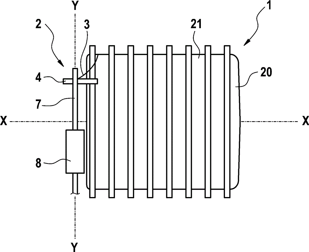
[0022] Refer below Figures 1 to 3 The electrical connection device 2 for the ignition coil 1 is described in detail.

[0023] as from figure 1 It can be seen in the figure that the ignition coil 1 according to the invention comprises an electrical connection device 2 and a coil body 20 with a plurality of surrounding chambers 21 in which enameled wire 3 is wound multiple times.

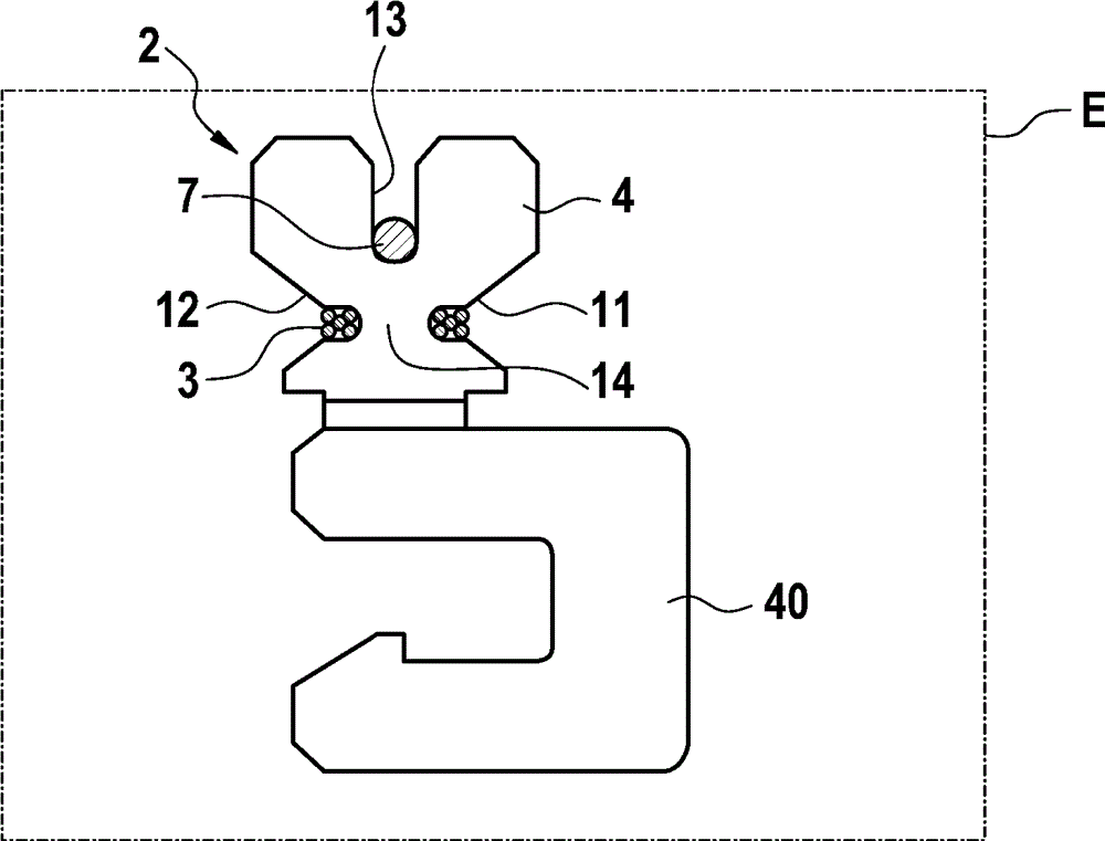
[0024] The electrical connection device 2 comprises a plate-shaped contact element 4 which is arranged only in the plane E. FIG. The contact element 4 has a first recess 11 and a second recess 12 which form a constriction region 14 between them. In this case, the first recess 11 and the second recess 12 are arranged opposite one another and have the same depth. as from figure 2 It can be seen that the enameled wire 3 is wound multiple times around the constriction region 14 and leads to the coil body 20 . Here, a first introduction region 15 and a second introduction region 16 for easier windin...


PUM


Abstract

The present invention relates to an electrical connection arrangement, particularly for an ignition coil, comprising an enamelled wire (3) enclosed in an insulating varnish, a contact element (4), and an electrical connecting wire (7), wherein the enamelled wire (3) and the connecting wire (7) make electrical contact with the contact element (4) and the contact element (4) has at least a first recess (11) and a second recess (12), which form a necked area (14) between themselves around which the enamelled wire (3) is wound, wherein an alignment of the enamelled wire (3) is on a base region (41, 42) of the first and the second recess (11, 12) parallel to an alignment of the connecting wire (7) on the contact element (4).

Description

technical field [0001] The invention relates to an electrical connection device, in particular for an ignition coil and in particular for electrical contacting of thin wires surrounded by varnish. Furthermore, the invention relates to an ignition coil and a method for forming a cold contact on an ignition coil. Background technique [0002] Ignition coils are known in various designs from the prior art. The usual methods of contacting the thin enameled wires in ignition coils are generally thermal methods, for example soldering or different welding methods. Furthermore, DE 10251841 A1 discloses a cold contact, in which a contact spring is lifted by a coil of enameled wire and engaged by a spring-like structure, so that an element arranged on the contact spring breaks through the insulation of the enameled wire for electrical connection. In some cases, however, electrical contacting by means of the snapping process is problematic. Furthermore, it is occasionally necessary ...

Claims


Application Information

Patent Timeline
Patent Type & Authority Applications(China)
IPC IPC(8): H01F5/04H01F38/12H01R4/10H01F27/28H01R4/14H01R4/24
CPCH01F27/2828H01F38/12H01F5/04H01R4/48
Inventor K. 林登塔尔K. 卡拉曼
Owner ROBERT BOSCH GMBH
Why Eureka
Try Eureka