Supercharge Your Innovation With Domain-Expert AI Agents!

Separator for energy storage device, laminated body, and porous membrane

A technology for electrical storage equipment and separators, which is applied in the field of separators for electrical storage equipment, laminates and porous membranes, and can solve the problems of insufficient adhesion and insufficient bonding between reactive polymers and porous membranes

Active Publication Date: 2015-03-18
ASAHI KASEI KK
View PDF7 Cites 20 Cited by
  • Summary
  • Abstract
  • Description
  • Claims
  • Application Information

AI Technical Summary

Problems solved by technology

[0013] However, the separator of Patent Document 1 has a problem in that the adhesiveness between the reactive polymer and the porous membrane is insufficient, and therefore, the adhesion to the electrodes is insufficient.

Method used


Image

  • Separator for energy storage device, laminated body, and porous membrane
  • Separator for energy storage device, laminated body, and porous membrane
  • Separator for energy storage device, laminated body, and porous membrane

Examples


no. 1 Embodiment approach

[0052] [Separators for electrical storage devices]

[0053] The separator for an electrical storage device (hereinafter, simply referred to as a "separator") according to the present embodiment has:

[0054] a polyolefin microporous membrane (hereinafter also simply referred to as "microporous membrane"), and a thermoplastic polymer covering layer covering at least a part of the surface of at least one side of the polyolefin microporous membrane,

[0055] The thermoplastic polymer covering layer is a layer in which a portion containing the thermoplastic polymer and a portion not containing the pre-thermoplastic polymer are present in the form of sea islands on the polyolefin microporous membrane,

[0056] the thermoplastic polymer contained in the aforementioned thermoplastic polymer cover layer has at least 2 glass transition temperatures,

[0057] At least one of the aforementioned glass transition temperatures exists in the region of less than 20°C,

[0058] At least one of...

no. 2 Embodiment approach

[0252] The porous membrane of this embodiment

[0253] having: a polyolefin microporous membrane, and a thermoplastic polymer cover layer covering at least a part of the surface of at least one side of the polyolefin microporous membrane,

[0254] The glass transition temperature of the thermoplastic polymer contained in the thermoplastic polymer covering layer is -10°C or more and 40°C or less, and

[0255] The degree of swelling of the thermoplastic polymer with respect to the electrolytic solution is 5 times or less.

[0256] In the second embodiment, other aspects are the same as those described in the first embodiment except for the aspects described later.

[0257] (glass transition temperature)

[0258] The thermoplastic polymer of the present embodiment has a glass transition temperature of preferably -10°C to 40°C, more preferably 0°C to 35°C, still more preferably 15°C to 30°C. In this embodiment, when the glass transition temperature of the thermoplastic polymer ...

Embodiment

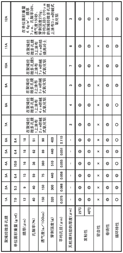
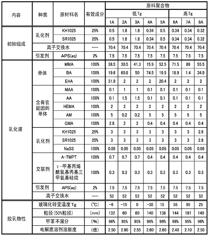
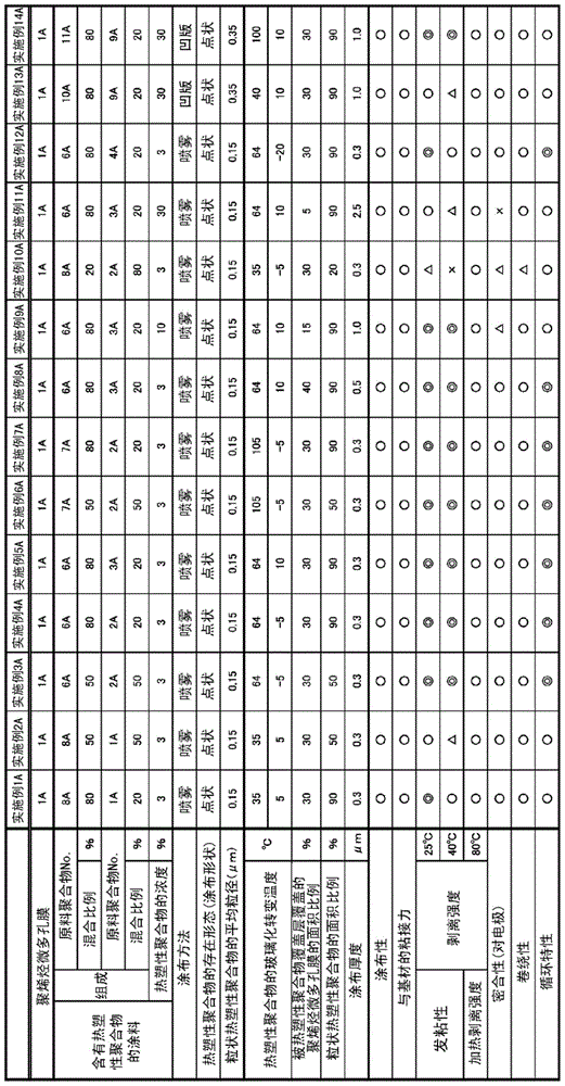
[0272] Hereinafter, although this invention is demonstrated more concretely based on an Example and a comparative example, this invention is not limited to these Examples. The measurement methods and evaluation methods of various physical properties used in the following production examples, examples, and comparative examples are as follows. In addition, unless otherwise specified, various measurements and evaluations were performed under the conditions of room temperature 23 degreeC, 1 atmospheric pressure, and 50% of relative humidity.

[0273] [test methods]

[0274] (1) Viscosity average molecular weight (hereinafter also referred to as "Mv".)

[0275] Based on ASRM-D4020, the intrinsic viscosity [η] at 135° C. using a decalin solvent was obtained, and Mv of polyethylene was calculated by the following formula.

[0276] [η]=0.00068×Mv 0.67

[0277] In addition, Mv of polypropylene was calculated|required by the following formula.

[0278] [η]=1.10×Mv 0.80

[0279] (...


PUM

PropertyMeasurementUnit
glass transition temperatureaaaaaaaaaa
peel strengthaaaaaaaaaa

Abstract

The purpose of the present invention is to provide a separator for an energy storage device having excellent adhesion to an electrode, and excellent handling properties. The separator for the energy storage device has a microporous polyolefin membrane, and a thermoplastic polymer covering layer that covers at least part of at least one of the surfaces of the microporous polyolefin membrane. In the thermoplastic polymer covering layer, an area that contains the thermoplastic polymer and an area that does not contain the thermoplastic polymer exist in a sea island form on the microporous polyolefin membrane. The thermoplastic polymer contained in the thermoplastic polymer covering layer has at least two glass transition temperatures. At least one of the glass transition temperatures exists in a region of less than 20°C, and at least one of the glass transition temperatures exists in a region of 20°C or above.

Description

technical field [0001] The present invention relates to a separator for an electrical storage device, a laminate, and a porous film. Background technique [0002] In recent years, the development of nonaqueous electrolyte batteries centered on lithium ion batteries has been actively developed. Generally, in a nonaqueous electrolyte battery, a microporous membrane (separator) is disposed between positive and negative electrodes. Such a separator has the function of preventing direct contact between positive and negative electrodes, allowing the electrolyte solution held in the micropores to pass through, and thereby allowing ions to permeate. [0003] In order to improve the cycle characteristics and safety of non-aqueous electrolyte batteries, the improvement of separators has been studied. For example, Patent Document 1 proposes to prepare a porous film carrying a binder by coating a reactive polymer on a porous film and drying it in order to provide a secondary battery h...

Claims


Application Information

Patent Timeline
Patent Type & Authority Applications(China)
IPC IPC(8): H01M2/16H01G11/52H01M50/417H01M50/443H01M50/449H01M50/489H01M50/491
CPCH01M2/1686Y02E60/13H01G11/52H01M2/1653H01M2/1673H01M50/46H01M50/449H01M50/443H01M50/491H01M50/489H01M50/417Y10T156/10Y02E60/10H01M50/414H01M10/052B32B37/182B32B2457/10
Inventor 宫泽博饴山圭太郎首藤乔
Owner ASAHI KASEI KK
Features
  • R&D
  • Intellectual Property
  • Life Sciences
  • Materials
  • Tech Scout
  • Unparalleled Data Quality
  • Higher Quality Content
  • 60% Fewer Hallucinations
Learn More