
Wear prevention reaction kettle

A technology for preventing wear and reaction kettles, which is applied in the field of wear prevention reaction kettles, can solve problems such as poor radial fluidity, poor mixing effect of material and liquid, and influence on heat transfer, so as to reduce the generation of air bubbles, improve the mixing effect, and improve agitation degree of effect

Inactive Publication Date: 2015-03-25
NINGBO YUANOU FINE CHEM
View PDF4 Cites 5 Cited by
  • Summary
  • Abstract
  • Description
  • Claims
  • Application Information

AI Technical Summary

Problems solved by technology

The agitator is an important part in the reaction kettle. The existing agitator adopts a paddle agitator. When working, the material rotates around the shaft, and the radial fluidity of the material from the periphery to the paddle area is poor, and the mixing effect is relatively poor. In addition, The disturbance of the bottom liquid is small, and the mixing effect of this part of the liquid is even worse
Moreover, the traditional agitator will generate a lot of air bubbles when stirring, which will cause part of the mixture to be wrapped in the air bubbles, causing the mixture to not be fully mixed.
[0003] At the same time, during the reaction process, the reaction products tend to be adsorbed on the inner wall of the kettle, which not only affects heat transfer, but also causes damage to the kettle body over time. Therefore, a stirring device with a stirring frame appears on the market, which can be used during stirring At the same time, scrape off the adsorbate accumulated on the inner wall of the kettle
However, excessive friction between the stirring frame and the inner wall of the kettle damages the kettle body

Method used


Image

  • Wear prevention reaction kettle
  • Wear prevention reaction kettle

Examples


Embodiment Construction

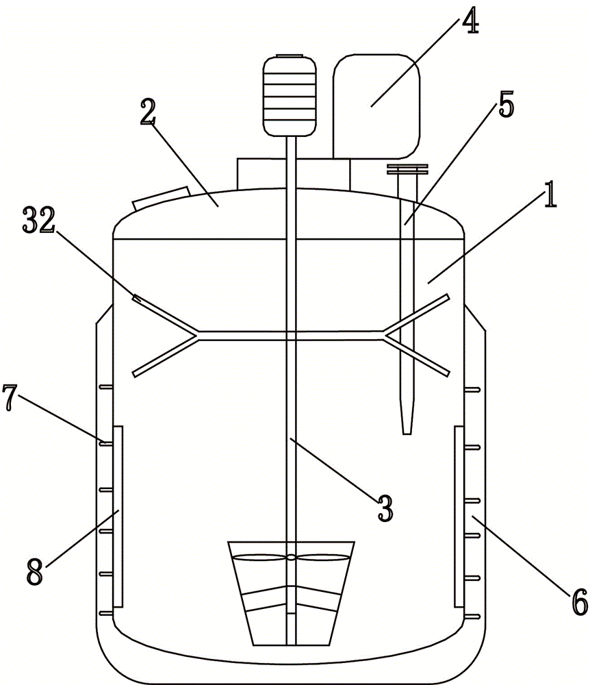
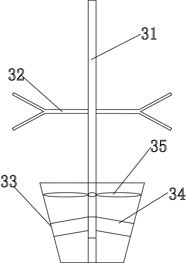
[0012] The present invention will be described in further detail below in conjunction with accompanying drawing and specific embodiment: see figure 1 , figure 2 , a reaction kettle for preventing abrasion, comprising a kettle body 1, a kettle cover 2 and a stirring device, characterized in that: the upper end of the kettle body 1 is provided with a feed inlet, and the lower end of the kettle body 1 is provided with a discharge outlet, so The stirring device includes a stirrer 3, a transmission device, an air pump 4, a shaft seal and a support seat, the stirrer 3 is located inside the kettle body 1, and the air pump 4, the shaft seal and the support seat are located in the On the kettle cover 2, it is connected with the agitator 3 through the transmission device, the thermometer sleeve 5 extends into the kettle body 1 and the upper end is fixed on the kettle cover 2, and the thermometer sleeve 5 is equipped with a thermometer , the agitator 3 includes a stirring shaft 31, a Y...


PUM

PropertyMeasurementUnit
Thicknessaaaaaaaaaa

Abstract

The invention discloses a wear prevention reaction kettle which comprises a kettle body, a kettle cover, a U-shaped jacket and a stirring device, wherein the stirring device comprises a stirrer, a transmission device, an air pump, a shaft seal and a supporting seat; the stirrer is positioned inside the kettle body; the air pump, the shaft seal and the supporting seat are positioned on the kettle cover and are connected with the stirrer by virtue of the transmission device; a thermometer well stretches into the kettle body, and the upper end of the thermometer well is fixedly arranged on the kettle cover; the stirrer comprises a stirring shaft, a Y-shaped gas ejector pipe, a ring duct, a stator and a rotor; the air pump is connected with the Y-shaped gas ejector pipe by virtue of a hose; the stator is positioned behind the rotor; the kettle comprises a cylinder and an elliptical lower seal head; the cylinder and the elliptical lower seal head are encircled by the U-shaped jacket; and a spirally ascending batten is wound around the outer wall of the cylinder. According to the wear prevention reaction kettle disclosed by the invention, the adsorbate accumulated on the inner wall of the kettle body can be removed so as not to damage the kettle body; and moreover, bubbles can be reduced during stirring, and full contact between the mixtures is maintained.

Description

technical field [0001] The invention relates to the field of mechanical accessory parts, in particular to a reaction kettle for preventing abrasion. Background technique [0002] Reactor is one of the essential equipment in the production of chemical industry. As we all know, there are many kinds of reactors, which are widely used in petroleum, chemical industry, food, medicine, pesticide, scientific research and other industries. They are used to complete polymerization, condensation, vulcanization, Reaction equipment for chemical processes such as alkylation and hydrogenation. The agitator is an important part in the reaction kettle. The existing agitator adopts a paddle agitator. When working, the material rotates around the shaft, and the radial fluidity of the material from the periphery to the paddle area is poor, and the mixing effect is relatively poor. In addition, The disturbance of the still bottom liquid is small, and the mixing effect of this part of the liquid...

Claims


Application Information

Patent Timeline
IPC IPC(8): B01J19/18B01J19/20
CPCB01J19/0053B01J19/0066B01J19/18B01J19/20B01J2219/185
Inventor 王淑英
Owner NINGBO YUANOU FINE CHEM
Learn More