Stirred tank reactor for cutting fluid

A technology for stirring reaction kettle and cutting fluid, applied in the field of chemical machinery and equipment, can solve the problems of weak liquid stirring ability, uniform mixing of unfavorable reactants, etc.

Active Publication Date: 2015-03-25
CHONGQING THRIVE CHEM
View PDF14 Cites 4 Cited by
  • Summary
  • Abstract
  • Description
  • Claims
  • Application Information

AI Technical Summary

Problems solved by technology

[0005] The agitator set in the Chinese patent CN203648523 mainly acts on individual horizontal surfaces, and the stirring effect is mainly concentrated on the liquid mixing in the stratosphere. The agitator has a weak ability to stir the liquid in the height direction of the entire reactor, which is not conducive to the uniform mixing of reactants

Method used


Image

  • Stirred tank reactor for cutting fluid
  • Stirred tank reactor for cutting fluid

Examples


Embodiment 1

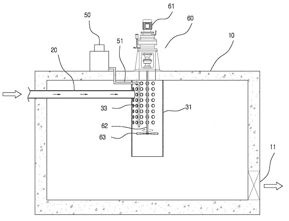
[0024] like figure 1 As shown, the stirring reactor for cutting fluid of the present invention includes a reactor body 10, an upper cover 60 arranged on the reactor body 10 and a motor 61 arranged on the upper cover 60, and the output of the motor 61 is The shaft passes through the upper cover 60 and intervenes in the kettle body 10 .

[0025] The stirring reaction kettle for cutting fluid of the present invention includes a stirring paddle 63 arranged in the kettle body 10, the stirring paddle 63 is connected to the output shaft of the motor 61, and a drainage tube 31, and the upper cylinder port of the drainage tube 31 is connected to On the inner wall of the kettle body 10 below the upper cover 60 , a stirring paddle 63 is arranged in the drainage tube 31 .

[0026] Under the premise of meeting the strength and rigidity requirements, the drainage tube 31 is made of light materials as much as possible to achieve the purpose of reducing the weight. In this embodiment, thick ...

Embodiment 2

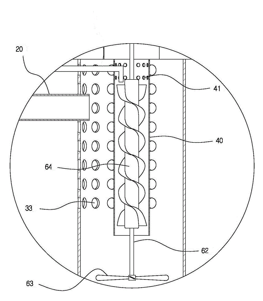
[0032] like figure 2 As shown, the difference between this embodiment and Embodiment 1 is that this embodiment also includes a drainage tube 40 disposed in the drainage tube 31, the connecting shaft 62 is disposed in the drainage tube 40, and on the connecting shaft 62 An auger blade 64 is provided, the upper and lower openings of the drainage tube 40 are fixed, and the upper opening is fixed on the inner wall of the kettle body 10, the drainage tube 51 penetrates into the drainage tube 40, and the nozzle of the drainage tube 51 Above the auger blade 64, a small drainage hole 41 is provided on the side wall of the drainage tube 40 above the mouth of the feed tube 20 at a height position, where the small drainage hole 41 is twelve times the diameter of the drainage tube 40. between one-tenth and one-tenth.

[0033] like figure 1 , 2 As shown, there is no drainage hole 33 on the side wall of the drainage tube 31 facing the nozzle of the feed pipe, so as to prevent the raw ma...


PUM


Abstract

The invention relates to chemical machinery equipment and in particular relates to a stirred tank reactor for cutting fluid. The stirred tank reactor for cutting fluid comprises a reactor body, a feeding pipe, and a stirring paddle arranged in the reactor body, and also comprises a drainage cylinder, wherein the stirring paddle is connected with an output shaft of a motor; the upper cylindrical opening of the drainage cylinder is connected to the inner wall of the reactor body below an upper cover; the stirring paddle is arranged in the drainage cylinder; a drainage hole is formed in the cylindrical bottom of the drainage cylinder; the stirring paddle comprises a spiral fan blade and a connecting shaft which is fixedly connected with the output shaft of the motor; the spiral fan blade is fixedly arranged on the connecting shaft; and the drainage hole is formed in the cylindrical wall of the drainage cylinder positioned above the spiral fan blade at a height position. According to the stirred tank reactor disclosed by the invention, the defect of mixing non-uniformity existing in the prior art is overcome, and due to the stirred tank reactor provided by the invention, reactants are uniformly mixed by virtue of flow of the fluid in the height direction.

Description

technical field [0001] The invention relates to chemical machinery equipment, in particular to a stirring reaction kettle for cutting fluid. Background technique [0002] There are generally two types of reaction equipment used in the production of cutting fluids, stirred reactors and tubular reactors, among which stirred reactors are the most widely used. Among them, the stirred reactor is characterized by large phase contact area, high mass transfer and heat transfer efficiency, low temperature, high operational flexibility (interval operation, semi-batch operation, continuous operation), and easy control and change of reaction conditions. [0003] Stirring in a stirred reactor plays a critical role. Stirring action: mix two or more miscible liquids evenly; form emulsion or suspension. The difference in the type of agitator has a great influence on the stirring effect. One of the cores of reactor scale-up is the scale-up of the stirrer. [0004] Yet existing agitator m...

Claims


Application Information

Patent Timeline
Patent Type & Authority Applications(China)
IPC IPC(8): B01J19/20
CPCB01J19/20Y02P70/10
Inventor 赵华文
Owner CHONGQING THRIVE CHEM
Why Eureka
Try Eureka