Fluidized electric separation device

A fluidization and electro-separation technology, which is applied in electrostatic effect separation, chemical instruments and methods, solid separation, etc., can solve the problems of complex structure of electro-separation equipment and insufficient charging of materials, and achieves good separation effect and high charging efficiency. The effect of good electrical effect and simple equipment

Active Publication Date: 2015-03-25
CHINA UNIV OF MINING & TECH
View PDF6 Cites 6 Cited by
  • Summary
  • Abstract
  • Description
  • Claims
  • Application Information

AI Technical Summary

Problems solved by technology

The main electric separators include drum electric separators, corona electric separators, rotary friction electric separators, sliding plate electric separators, etc., and there are problems of insufficient charging of materials and charge consumption of particles entering the sorting part through the charged part. Insufficient, and the structure of electric separation equipment is complex

Method used


Image

  • Fluidized electric separation device
  • Fluidized electric separation device
  • Fluidized electric separation device

Examples


Embodiment

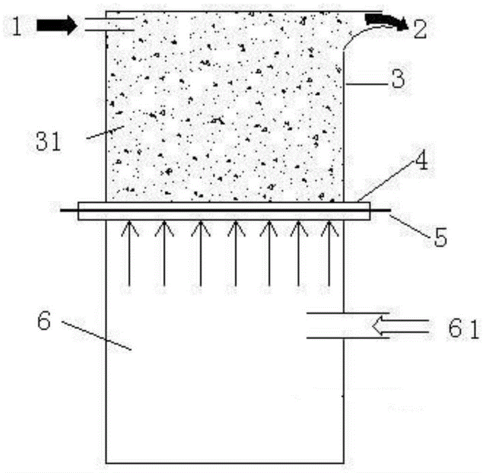
[0024] The powder material is sent into the fluidized bed 31 of the fluidized electric separator body 3 through the feeder through the feed port, the air supply system 61 is opened, and a fan is used to supply air to the fluidized electric separator body 3, and the wind force is from the supply The air system 61 enters the air chamber 6 through the pipe, and then enters the fluidized bed 31 through the air distribution plate 5, and supplies air to the inside of the fluidized bed 31 to fluidize the material. The air distribution plate 5 adopts an orifice plate with air permeability The material, which can be textile or perforated ceramic plate, can be determined by yourself.

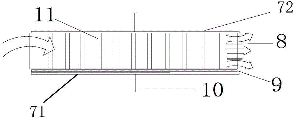
[0025] The front and rear side inner walls of the fluidized bed 31 are conductive front electrode plates 71 and rear electrode plates 72, the front electrode plates 71 and the rear electrode plates 72 are conductive metal material plates, and the front and rear electrode plates 71 , 72 electrode plates ar...


PUM


Abstract

The invention discloses a fluidized electric separation device which comprises a fluidized electric separation device body, a high-pressure power supply and an air supply system. An air chamber of the fluidized electric separation device body is connected with the air supply system through a pipe. The fluidized electric separation device body comprises a fluidized bed, an air distributor, the air chamber, a feeding inlet and a discharging outlet. The feeding inlet and the discharging outlet are formed in the two ends of the fluidized bed respectively. A material distribution plate is arranged in the discharging outlet in the horizontal direction. Electrode plates are arranged on the inner walls of the two sides of the fluidized bed. the inner sides of the two electrode plates or the inner side of one electrode plate are / is exposed or provided with an insulating partition, and the electrode plates are connected with the positive pole and the negative pole of the high-voltage power supply respectively; or one side of each electrode plate is connected with the power supply, and the other side of each electrode plate is connected with the ground. A friction bar set is arranged in the fluidized bed in the axial direction. Powder material is in full friction with friction bars in the fluidized bed and the electrode plates or the insulating partition to be fully charged, or the powder material is in conduction sensing with the friction bars in the fluidized bed and the electrode plates or the insulating partition to be fully charged. The electric charging requirement in the separation process is met, the material charging effect is good, separation efficiency is high, the process is simple, energy consumption is low, and the device is simple.

Description

technical field [0001] The invention belongs to the technical field of dry separation of solid materials, and in particular relates to a fluidized electric separation device. Background technique [0002] Powder is a solid in a special form, and the generation of static electricity conforms to the basic principle of a double electric layer. During the frictional electrification process of powder, there is also a process in which the charge is released through the wall of the device, the wall of the pipe, the tooling, the equipment and even the atmosphere. [0003] There are many factors that affect the static electricity generated by powder materials in the process of motion friction, such as the properties of powder materials, including their chemical composition, particle size, deformation state, and surface geometric characteristics; chemical structure, conductivity of the wall material in contact with the material; contact The size of the surface, the contact time, the ...

Claims


Application Information

Patent Timeline
Patent Type & Authority Applications(China)
IPC IPC(8): B03C7/00
Inventor 王海锋杨兴何亚群张光文张亚恒侯浩张伟刚
Owner CHINA UNIV OF MINING & TECH
Why Eureka
Try Eureka