[0047] The present invention will be further described below with reference to the accompanying drawings and embodiments.
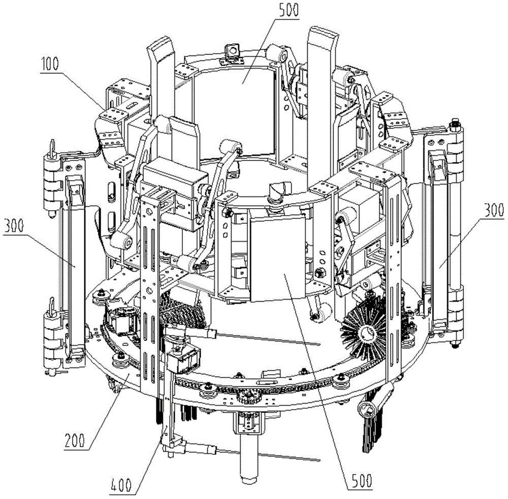
[0048] like figure 1 As shown, the robot as a whole has a circular structure, including a crawling mechanism 100 , a cleaning mechanism 200 , a locking mechanism 300 , a detection mechanism 400 and a battery control system 500 . The crawling mechanism 100 and the cleaning mechanism 200 are connected by the locking mechanism 300 , the detection mechanism 400 is arranged on one side of the locking mechanism 300 , and the battery control system 500 is arranged on the crawling mechanism 100 .
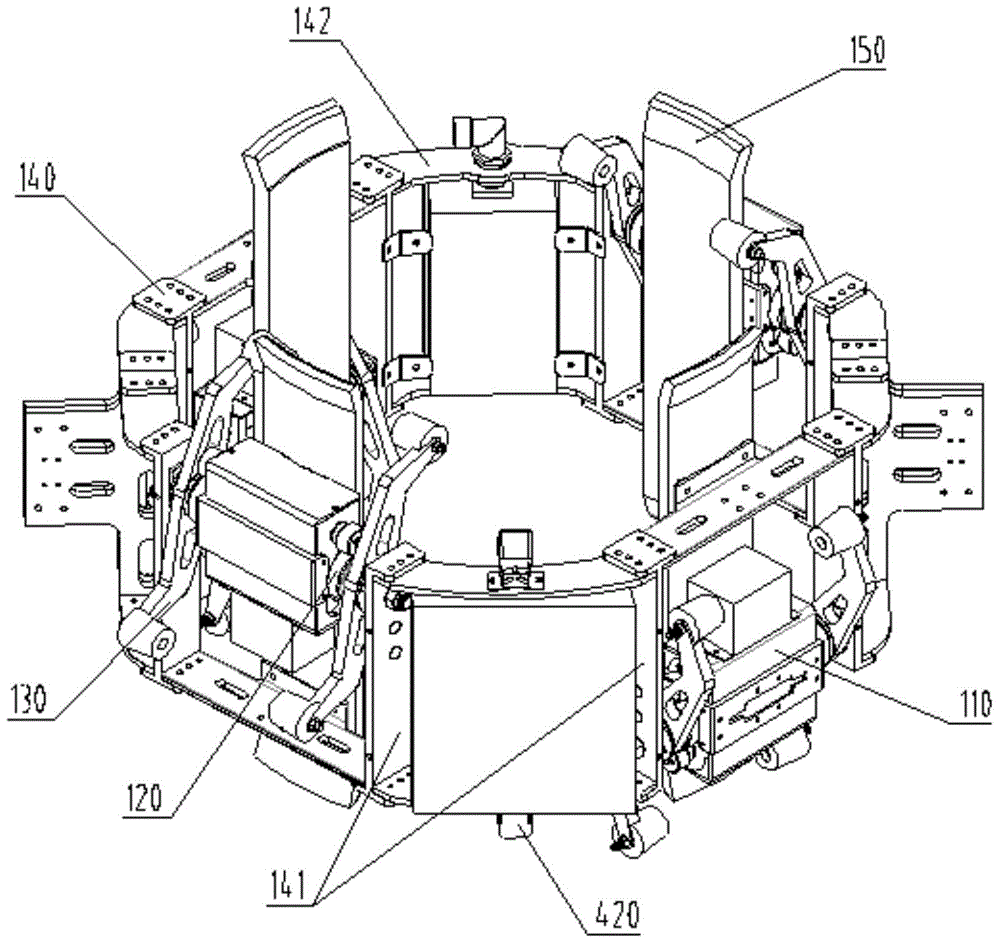
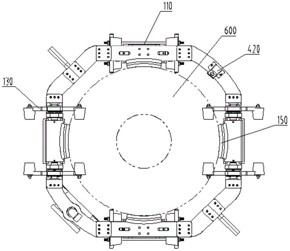
[0049] like figure 2 , image 3 , Figure 4 As shown, the robot crawling mechanism 100 is a closed circular structure, surrounds the insulator strings, can be opened and closed, and is mainly composed of a driving mechanism 110, a connecting mechanism 140 and a number of guide plates 150. The driving mechanism 110 is symmetrically connected through the connecting mechanism 140, and the insulator The sheet is symmetrical in the radial plane, and each driving mechanism 110 corresponds to a set of guide plates 150 , and the inner diameter of the guide plates 150 fits the outer diameter of the insulator sheet. The driving mechanism 110 includes a driving motor 111, a transmission mechanism 120, a driving gripper mechanism 130, and a fixed frame 112. The driving motor 111 is installed inside the fixed frame 112, and the transmission mechanism 120 and the driving gripper mechanism 130 are installed outside the fixed frame 112. The frame 112 is mounted on the circumference formed by the guide plate 150 . Each group of driving mechanisms 110 is composed of at least one driving motor 111 driving at least one group of driving grippers 131. The output shaft of the driving motor 111 is connected to the transmission mechanism 120. The transmission mechanism 120 is a gear reducer device, which mainly includes a driving gear 121 and a driven gear. 122. The fixed shaft 123, the transmission shaft 124, the output end of the transmission mechanism 120 is connected with the driving gripper mechanisms 130 on both sides, and the end of the driving gripper 131 is installed with a roller 132, the roller 132 can rotate freely, and the roller 132 is in contact with the insulator 600 during the crawling process . The connecting mechanism 140 includes a vertical bracket 141 and various annular brackets 142, and is connected to each driving mechanism 110 to form an annular whole, such as figure 2 As shown, the vertical support 141 is connected to the axial drive mechanism 110 , the annular support 142 is connected to the radial drive mechanism 110 , and the vertical support 141 has adjustment mounting holes for adjusting the distance between the axial drive mechanisms 110 .
[0050] like Figure 5 , Image 6 As shown, the robot cleaning mechanism 200 is also a closed circular structure as a whole, surrounds the insulator 600, and can be opened and closed. The cleaning mechanism 200 mainly includes a left-right symmetrical half-disk 210 , an up-down symmetrical rack 220 , a rack drive mechanism 230 , a rack guide 240 , an upper brush mechanism 250 , a lower brush mechanism 260 and several guide rods 270 . The left and right symmetrical half discs 210 form a circumferential ring structure, which is the basic base of the cleaning mechanism 200. A number of guide rods 270 are installed in the inner arc, and symmetrical rack guide rails 240 and rack guide rails 240 are distributed on the upper and lower sides thereof. It is formed by several large roller bearing groups 241 and small roller bearing groups 242, such as Figure 5 , the large roller bearing group 241 forms an outer circular guide rail in the circumferential direction, and the small roller bearing group 242 forms an inner circular guide rail in the circumferential direction, which restricts the rack 220 within the prescribed rail plane. The racks 220 have a semi-circular structure and are symmetrically distributed on the upper and lower sides of the semi-circle 210 , that is, the upper and lower rack guide rails 240 correspond to one rack 220 respectively. The circular guide formed by the bearing group performs a synchronous circular motion. At least one set of rack driving mechanisms 230 is installed on each half-disk 210. When each half-disk 210 is designed to have one rack driving mechanism 230, in order to ensure that the semi-circular rack 220 is driven by two racks The mechanism 230 is connected smoothly, and the distribution angle of the two rack drive mechanisms 230 is less than 180°.
[0051] like Image 6 As shown, the rack drive mechanism 230 is fixed on the semi-circle 210 , and the rack drive mechanism 230 mainly includes a rack drive motor 231 , a symmetrical gear 233 , a gear shaft 234 and a motor base 232 . The rack drive motor 231 is fixed on the motor base 232, the motor base 232 is fixed on the semi-disc 210, the output shaft of the rack drive motor 231 is connected with the symmetrical gear 233 through the gear shaft 234, and the symmetrical gear 233 is respectively connected with the upper and lower symmetrical racks 220 meshes, and the rack drive motor 231 rotates to drive the upper and lower symmetrical racks 220 to perform synchronous circular motion.
[0052] like Figure 5 , Figure 7 , Figure 8 As shown, the upper brush mechanism 250 and the lower brush mechanism 260 are respectively installed on the upper and lower racks 220, and at least two sets of brush mechanisms are installed on each rack 220. Slightly different, the upper brush mechanism 250 is composed of a steering gear base 251, a steering gear 252, a brush motor 253, a brush motor base 254, an upper motor base connection 255, a shaft plate 257, and an upper brush 256. The lower brush mechanism 260 consists of a steering gear base 251, a steering gear 252, a brush motor 253, a brush motor base 254, a lower motor base connection 261, a shaft plate 257, and a lower brush 262. There are two types of brushes, upper and lower brushes, which are specifically designed to conform to the structure of the cleaning surface of the insulator sheet. The brush is connected to the end of the output shaft of the brush motor 253 through the shaft disc 257 , the brush motor 253 is fixed inside the brush motor base 254 , and is connected and fixed to the steering gear 252 through the motor base, and the steering gear 252 is fixed through the steering gear base 251 On the rack 220, when the output shaft of the steering gear 252 rotates, it drives the brush to swing on the radial surface of the insulator sheet, and when the output shaft of the brush motor 253 rotates, it drives the brush to rotate along its own axis.
[0053] like figure 1 , Figure 9 As shown, the locking mechanism is divided into left and right parts, one is the hinged rotation center, around which the robot rotates to open and close, and the other is the locking switch. like Figure 9 The hinge of the hinged rotation center rotates around the hinge axis, and the hinge drives the left and right parts of the robot to open and close. The locking mechanism can be equipped with operating parts such as handles or lifting rings, which are convenient for operators to carry and go online.
[0054] like figure 1 , image 3 , Figure 4 , Figure 5 As shown, the robot inspection mechanism includes a camera, a limit device and an insulator inspection device. The camera is used to monitor the running status of the crawling mechanism and the cleaning brush, the limit device limits the robot's moving position and the cleaning and detection position, and the insulator detection device can detect the resistance and voltage of the insulator.
[0055] like figure 1 , As shown in Figure 10, the insulator detection device is mainly composed of a probe driving mechanism, a fixing frame and a detection probe, which is installed on one side of the cleaning mechanism. The probe driving mechanism includes a driving steering gear, a swing arm, a crank connecting rod, a rotating shaft, etc. , There are at least two detection probes, and the distance between the adjacent probes is the axial length of the two insulators. The rotation of the output shaft of the steering gear drives the detection probes to swing back and forth, hitting the steel caps of the two adjacent insulators.
[0056] The working principle of the present invention:
[0057] When the present invention does not work, the crawling mechanism, the cleaning mechanism and the detection mechanism are in the initial state, the driving claws of the upper and lower driving mechanisms of the crawling mechanism are in the vertical state, and the semicircular boundary of the cleaning mechanism rack and the semicircular boundary of the semi-disc coincide (eg Figure 5 shown), the upper and lower brush mechanisms are retracted to the direction of tangent to the circumferential guide (such as Figure 5 The left brush position), the detection probe is also in a retracted state (as shown in Figure 10(a)), the locking mechanism is in a closed state, and the robot as a whole is in a circular closed state.
[0058] The robot can use a pulley block and a hoisting mechanism to rise to the vicinity of the tower insulator string through the handle of the locking mechanism and other hoisting components, turn on the robot battery control system, and open the locking mechanism. Here, the hinged rotation center of the locking mechanism can be a simple hinged opening and closing The mechanism can also be designed to drive the motor to drive the folding to rotate to complete the opening and closing action of the robot. Correspondingly, the locking switch can be a simple pin-type structure, or can be designed as a motor-driven pin-pin method or a clamp lock.
[0059] Adjust the opening position of the robot, use the insulating rod and other auxiliary tools to push the robot into the insulator string, start the closing switch, and lock the robot on the insulator string. At this time, the inner circular guide plate of the crawling mechanism and the inner circular guide rod of the cleaning mechanism are in contact with the insulator string and parallel. Around the outer circumference of the insulator string, adjust the position of the driving claw of the crawling mechanism, so that at least one layer of the driving claw of the upper and lower driving mechanism overlaps the upper surface of the insulator string. At this time, the robot is installed on the insulator string.
[0060]At the beginning of the robot operation, the upper and lower driving mechanisms of the crawling mechanism are controlled alternately to complete the crawling process, and the limit device on it can precisely control the rotation angle of the driving gripper, locate the cleaning and detect the position. When the robot moves to the predetermined cleaning position, the cleaning program is started and the cleaning operation is performed. First, the upper and lower brush mechanisms rotate the steering gear shaft, swing the upper and lower brushes into the diameter of the insulator disc, and make the brush axis point to the insulator string axis. The built-in rotary motor of the upper and lower brushes starts, and drives the upper and lower brushes to rotate. At this time, only the rotation of the brushes is completed. Then the motor of the rack drive mechanism starts to drive the upper and lower symmetrical gears to rotate synchronously, and the upper and lower symmetrical gears mesh with the upper and lower symmetrical gears. The rack moves in a circle within the range of the rack guide, driving the upper and lower brushes to clean the insulator sheet. At least one set of rack drive mechanisms is installed on each half-disk. When each half-disk is designed to have one rack drive mechanism, in order to ensure smooth connection of the semi-circular racks when passing through the two rack drive mechanisms, The distribution angle of the two rack drive mechanisms is less than 180°. At this time, the brush for cleaning the insulator sheet needs to rotate back and forth twice to complete the cleaning operation. The cleaning operation of the insulator sheet can be completed by one rotation.
[0061] After completing the cleaning of a piece of insulator, the brush motor stops running, the brush steering gear swings the brush back to the original position, the rack drive mechanism rotates the rack to the original position, the crawling mechanism starts, and the up and down drive mechanism cooperates to drive the robot to move to the bottom. A piece of cleaning insulator sheet, under the action of the limit device, reaches the predetermined cleaning position, and then the cleaning mechanism drives the operation program to clean the next piece of insulator. This round-trip operation process finally completes the cleaning operation of the entire string of insulators.
[0062] In addition to cleaning operations, the robot can also perform inspection operations. The camera included on it is used to monitor the running status of the crawling mechanism and the cleaning brush. The limit device limits the movement position of the robot and the cleaning and inspection positions. The insulator detection device can measure the resistance of insulators. and voltage detection. These detection devices can monitor the operation status of the robot, the surface cracks and contamination of the insulator string, the surrounding hardware, determine the limit position and obtain the corresponding data of the insulator sheet.
[0063] The invention adopts a continuous moving method, with fast moving speed, good movement continuity, and an overall symmetrical structure, which does not cause eccentricity in the moving and cleaning process; the cleaning speed is fast, the cleaning is thorough, the cleaning method is simple and lightweight, and methods such as water washing are avoided. The operation difficulty and workload are small; the wear of the insulator coating is small, and the wear of the anti-pollution flashover coating on the insulator porcelain skirt is avoided; the locking is reliable, the safety protection is good, and the circular closing method is used to increase the working stability of the robot; It has adaptability. The distance between the axial drive mechanism of the robot crawling mechanism is designed to be adjustable, the distance between the upper and lower brushes of the cleaning mechanism is designed to be adjustable, and the length of the brush can be replaced, which can adapt to the cleaning of insulator strings with different structure heights and disk diameters. It can perform resistance and voltage detection for insulator strings to determine the quality of insulator sheets.
[0064] Although the specific embodiments of the present invention have been described above in conjunction with the accompanying drawings, they do not limit the scope of protection of the present invention. Those skilled in the art should understand that on the basis of the technical solutions of the present invention, those skilled in the art do not need to pay creative efforts. Various modifications or deformations that can be made are still within the protection scope of the present invention.