Combined clamping mechanism

A technology of clamping mechanism and side plate, applied in clamping, workpiece clamping device, metal processing mechanical parts, etc., can solve the problems of affecting the clamping effect, laborious, not tight clamping, etc.

Inactive Publication Date: 2015-03-25
常州恒源钢结构工程有限公司
View PDF0 Cites 8 Cited by
  • Summary
  • Abstract
  • Description
  • Claims
  • Application Information

AI Technical Summary

Problems solved by technology

[0002] In mechanical processing, the workpiece needs to be clamped first. Many existing fixtures push the clamping block by applying a force in the same direction as the clamping force to achie

Method used


Image

  • Combined clamping mechanism

Examples


Embodiment Construction

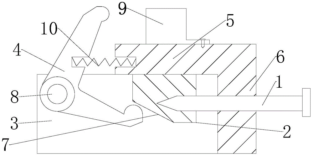
[0012] Depend on figure 1 It can be seen that a combined clamping mechanism of the present invention includes a body, a bolt 1, a wedge 2, a side plate 3 and a lever 4, the body includes an upper side plate 5 and a right side plate 6, and the upper side plate 5 and the right side The plate 6 has an integral structure, the right side plate 6 is provided with a threaded bolt 1, the lower surface of the upper side plate 5 is provided with a wedge 2, the left end of the bolt 1 extends into the wedge 2, and the wedge The left end of the block 2 is provided with an inclined surface 7, the inclined surface 7 is in contact with the lower end of the lever 4, the side plate 3 is provided with a rotating shaft 8, the lever 4 is sleeved on the rotating shaft 8, and the upper surface of the upper side plate 5 is fixed with screws There is a stopper 9, and a spring 10 is fixed on the left end of the upper side plate 5, and the left end of the spring 10 is fixedly connected with the upper ha...


PUM


Abstract

The invention relates to a combined clamping mechanism. The combined clamping mechanism comprises a body, a bolt, a wedge block, a side plate and a lever. The body comprises an upper side plate and a right side plate which are of an integrated structure. The right side plate is provided with the bolt in a thread fitting mode, and the wedge block is arranged on the lower surface of the upper side plate. The left end of the bolt extends into the wedge block, an oblique plane is arranged at the left end of the wedge block and is in contact with the lower end of the lever, the side plate is provided with a rotating shaft sleeved with the lever, and a check block is fixed to the upper surface of the upper side plate. By means of the structure, the wedge block is pushed leftwards by rotating the bolt, the lever clamps a workpiece on the upper side plate, the oblique plane of the wedge block is a big lift angle and does not need to be self-locked, rapid clamping is facilitated, the lever changes the direction of the action force, the action force is changed into the clamping force, and the bolt plays a role in force increasing.

Description

technical field [0001] The invention relates to a clamping mechanism, especially a combination clamping mechanism. Background technique [0002] In mechanical processing, the workpiece needs to be clamped first. Many existing fixtures push the clamping block by applying the force in the same direction as the clamping force to achieve the purpose of clamping the workpiece. This method is laborious, and It is easy to be affected by the rebound force and not clamp tightly, which affects the clamping effect. Contents of the invention [0003] The purpose of the present invention is to provide a combined clamping mechanism with simple and reasonable structure, labor saving and good clamping effect. [0004] The technical scheme that realizes the object of the present invention is as follows: [0005] A combined clamping mechanism, including a body, bolts, wedges, side plates and levers, the body includes an upper side plate and a right side plate, the upper side plate and the...

Claims


Application Information

Patent Timeline
IPC IPC(8): B23Q3/00
CPCB23Q3/06B25B11/00
Inventor 陈建强
Owner 常州恒源钢结构工程有限公司
Why Eureka
Try Eureka