Gear transmission swinging pressing mechanism

A technology of gear transmission and compression mechanism, which is applied in the direction of metal processing machinery parts, clamping, support, etc., can solve the problems of manual adjustment, unfavorable production efficiency, time-consuming and labor-intensive, etc., and achieve reliable compression, simple structure, and labor-saving hydraulic drive Effect

Inactive Publication Date: 2015-03-25
常州市锐金轮机械配件有限公司
View PDF0 Cites 19 Cited by
  • Summary
  • Abstract
  • Description
  • Claims
  • Application Information

AI Technical Summary

Problems solved by technology

[0002] There are many kinds of existing machine tool fixtures. To fix the workpiece on the machine tool table, the pressure plate fixture is generally used to position and compress the workpiece. Manual adjustment is required for clamping the workpiece, which is time-consuming and laborious, especially in mass production. Not conducive to the improvement of production efficiency

Method used


Image

  • Gear transmission swinging pressing mechanism

Examples


Embodiment Construction

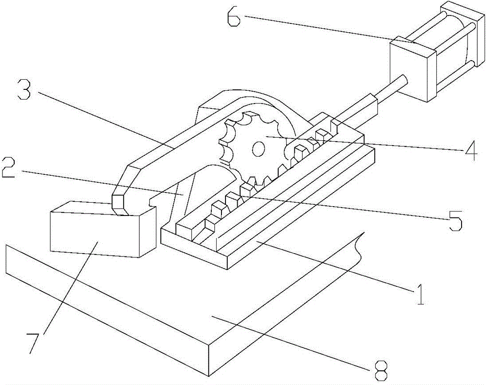
[0013] Such as figure 1 The gear-driven oscillating compression mechanism shown includes a fixed plate 1, a hydraulic cylinder 6, a pressure plate 3 and a gear 4. The fixed plate 1 is provided with a vertical vertical plate 2. The front end of the pressure plate 3 is straight and the rear end is bent downward. The front end of the pressing plate 3 is provided with a downward raised pressing block, and the surface of the raised pressing block is provided with anti-skid lines. The arc-shaped rear end of the pressing plate 3 is hinged with the vertical plate 2, and the gear 4 is fixed on the corresponding At the joint with the vertical plate 2, the axis of the gear 4 is in line with the axis of the joint. The gear 4 controls the pressure plate 3 to rotate synchronously. The fixed plate 1 corresponding to the bottom of the gear 4 is provided with a rack 5 meshing with the gear 4. Slidingly connected with the fixed plate 1, the hydraulic cylinder 6 is set on the rear side of the ra...


PUM


Abstract

The invention relates to the technical field of machine tool clamps, in particular to a gear transmission swinging pressing mechanism. The gear transmission swinging pressing mechanism comprises a fixing plate, a hydraulic cylinder, a pressing plate and a gear. The fixing plate is provided with a vertical stand plate, the front end of the pressing plate is in a linear shape, and the back end of the pressing plate is in an arc shape bent downwards. The gear is fixed to the arc back end of the pressing plate and controls the pressing plate to rotate synchronously. The arc back end of the pressing plate is hinged to the stand plate. A rack meshed with the gear is arranged on the part, corresponding to the bottom of the gear, of the fixing plate and connected with the fixing plate in a sliding mode. The hydraulic cylinder is arranged on the back side of the rack. A piston rod of the hydraulic cylinder is connected with the back end of the rack and controls the forward and backward movement of the rack, clamping is quick, labor is saved, pressing is reliable due to hydraulic driving pressing, and the clamp is simple in structure and low in cost.

Description

technical field [0001] The invention relates to the technical field of machine tool fixtures, in particular to a gear-driven swing pressing mechanism. Background technique [0002] There are many kinds of existing machine tool fixtures. To fix the workpiece on the machine tool table, the pressure plate fixture is generally used to position and compress the workpiece. Manual adjustment is required to clamp the workpiece, which is time-consuming and laborious, especially in mass production. It is not conducive to the improvement of production efficiency. Contents of the invention [0003] The technical problem to be solved by the present invention is to provide a gear-driven oscillating and pressing mechanism for the above-mentioned defects, fast and labor-saving clamping operation, hydraulically driven pressing, reliable pressing, simple structure of the clamp, and low cost. [0004] The technical scheme that the present invention solves its technical problem adopts is as ...

Claims


Application Information

Patent Timeline
Patent Type & Authority Applications(China)
IPC IPC(8): B23Q3/08
CPCB23Q3/082
Inventor 吴红燕孙祥龙
Owner 常州市锐金轮机械配件有限公司
Why Eureka
Try Eureka