Cylindrical grinding machine tailstock

A technology for cylindrical grinding machines and tailstocks, which is applied in the direction of grinding machines, machine tools designed for grinding workpiece rotating surfaces, grinding workpiece supports, etc., and can solve problems such as the axis line between the tip shaft and the workpiece spindle with a large impact force, and achieve The effects of improving stability, improving production efficiency, and improving machining accuracy

Inactive Publication Date: 2015-03-25
XINCHANG COUNTY HAILIPU SEIKO TECH
View PDF5 Cites 5 Cited by
  • Summary
  • Abstract
  • Description
  • Claims
  • Application Information

AI Technical Summary

Problems solved by technology

[0003] The purpose of the present invention is to overcome the defects that the top shaft of the tailstock of the existing grinding machine has a relatively large impact force on the workpiece end surface, and there is a certain slight deviation between the top shaft and the axis center line of the workpiece spindle, and provide a kind of impact force that is small and can effectively improve Tailstock of Cylindrical Grinder for Machining Accuracy

Method used


Image

  • Cylindrical grinding machine tailstock
  • Cylindrical grinding machine tailstock
  • Cylindrical grinding machine tailstock

Examples


Embodiment Construction

[0012] The specific embodiments of the present invention will be described in detail below with reference to the accompanying drawings.

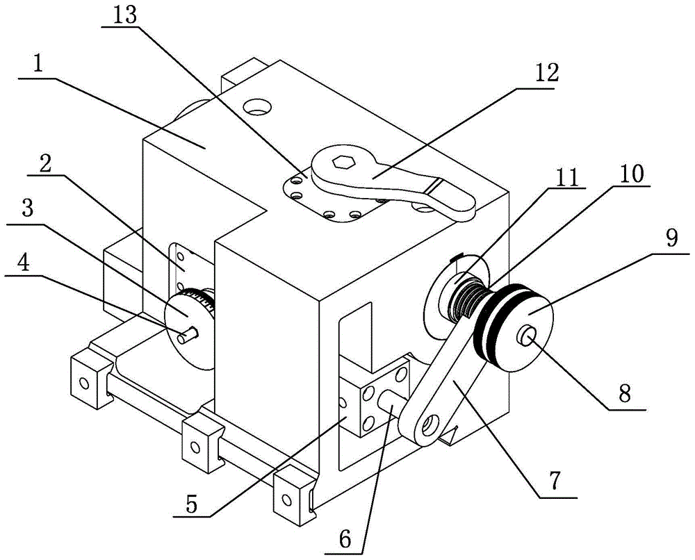
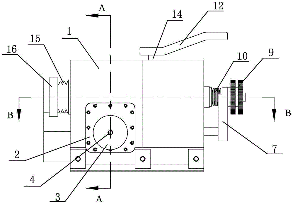
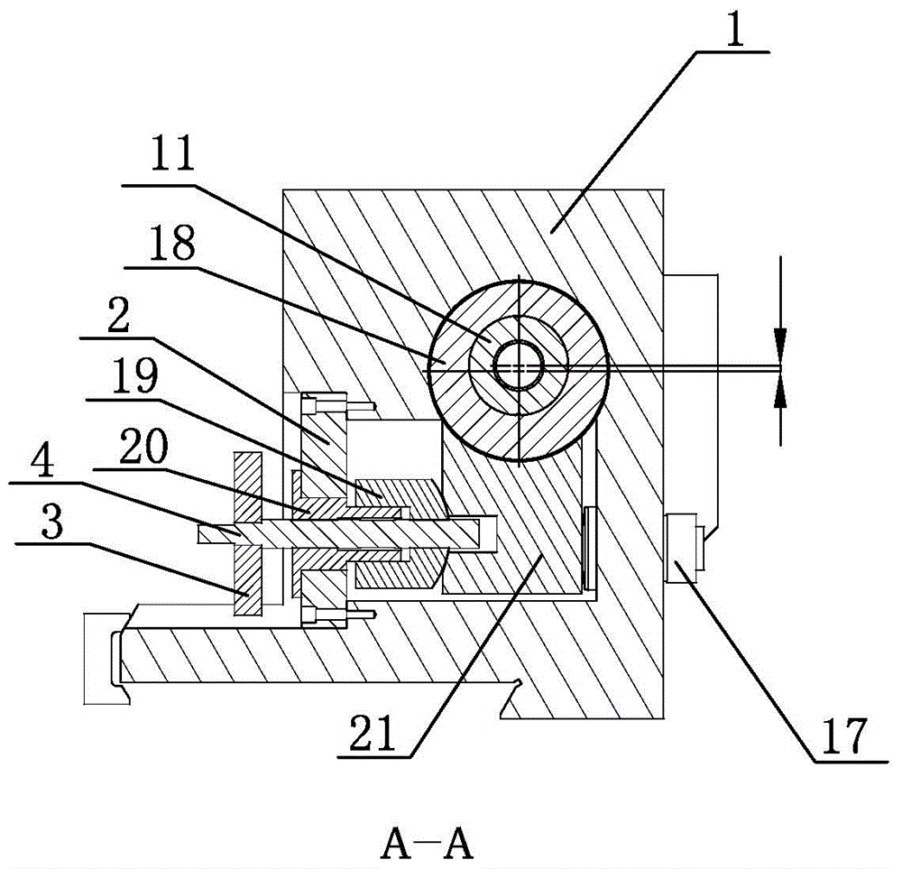
[0013] Such as Figure 1~Figure 4 As shown, the present invention includes a tailstock body 1, a top shaft, a top shaft sleeve 11, a manual control mechanism, a buffer spring 15, an automatic control mechanism, a middle eccentric sleeve 18 and a concentricity adjustment mechanism. The tailstock body 1 is provided with The through-hole is installed horizontally, the top shaft sleeve 11 is slidably inserted into the horizontal through-hole, the top shaft is inserted in the front end of the axial through hole of the top shaft sleeve 11, and the middle eccentric sleeve 18 is installed at the Between the center shaft sleeve 11 and the transverse installation through hole; the outer circular surface of the center shaft sleeve 11 close to the end of the workpiece is provided with an end shoulder facing the end, and the center shaft sleeve 11 faces the...


PUM


Abstract

The invention relates to a cylindrical grinding machine tailstock, and belongs to the technical field of machine tool accessories. An existing tailstock has the shortcomings that impact force of a center shaft to the end face of a workpiece is large, and a certain tiny deviation exists between the axial line of the center shaft and the axial line of a main shaft of the workpiece. The cylindrical grinding machine tailstock comprises a tailstock body, the center shaft, a center shaft sleeve, a manual control mechanism, a buffer spring, an automatic control mechanism, a middle eccentric sleeve and a concentricity adjusting mechanism. The end, facing the workpiece, of the center shaft sleeve is sleeved with the buffer spring, so that the impact force is reduced, and the buffer effect is achieved; an oil cylinder drives the center shaft sleeve to move in the axial direction and provide ejection force, so that the ejection force is stable; in addition, the oil cylinder and the manual control mechanism of a gear and rack pair structure exist at the same time; the center shaft sleeve is sleeved with the middle eccentric sleeve and the concentricity adjusting mechanism composed of a swing rod, a left push rod mechanism and a right push rod mechanism, the tiny displacement deviation between a center part of the center shaft and the axel line of the main shaft of the workpiece can be adjusted, adjustment is convenient, and the machining accuracy of the workpiece is improved.

Description

Technical field [0001] The invention belongs to the technical field of machine tool accessories, and is especially related to a cylindrical grinder tailstock. Background technique [0002] The workpiece spindle device and tailstock of the cylindrical grinder are installed on both ends of the workbench. The tailstock and the workbench are matched by a sliding groove and tenon structure. One end of the workpiece with a longer axial length is clamped by the workpiece spindle device, and the other end passes through Push the tailstock to drive the top shaft on the tailstock against the support, and then generate a certain force against the workpiece through manual control. The workpiece spindle device drives the workpiece to rotate, and the grinding wheel device processes the outer surface of the workpiece. During the leaning process, if the top axis on the tailstock moves faster, it is easy to produce a greater impact on the workpiece, which affects the processing accuracy of the ...

Claims


Application Information

Patent Timeline
Patent Type & Authority Applications(China)
IPC IPC(8): B24B41/06B24B5/02
CPCB24B5/02B24B41/06
Inventor 石云峰
Owner XINCHANG COUNTY HAILIPU SEIKO TECH
Why Eureka
Try Eureka