Cylindrical coordinate robot

A technology of cylindrical coordinates and robots, which is applied in the direction of manipulators, program-controlled manipulators, manufacturing tools, etc., can solve problems such as weak rigidity, large footprint, and uncompact structure, and achieve good stability and rigidity, and occupy an area Small, compact effect

Inactive Publication Date: 2015-03-25
CHONGQING LANGZHENG TECH
View PDF8 Cites 23 Cited by
  • Summary
  • Abstract
  • Description
  • Claims
  • Application Information

AI Technical Summary

Problems solved by technology

[0002] In today's processing and manufacturing industry, the loading and unloading of materials on the production line of many factories is still done manually, which is labor-intensive and low in production efficiency. In order to improve work efficiency, reduce labor costs, and adapt to modern automated production, a cylindrical coordinate robot is designed to replace manual loading and unloading. to increase labor productivity
The existing cylindrical coordinate robot mainly uses the screw transmission device to realize the translation of the material and the multi-axis rotation mechanism to realize the rotation of the material, and there is no mechanism to realize the material's own turnover. Finish
Moreover, the structure of the multi-axis rotating mechanism adopted by the existing cylindrical coordinate robot is too complicated, and the overall rigidity of the structure is weak, so that the existing cylindrical coordinate robot has a complex structure, weak rigidity and large footprint on the whole. Disadvantages such as not compact structure

Method used


Image

  • Cylindrical coordinate robot
  • Cylindrical coordinate robot
  • Cylindrical coordinate robot

Examples


Embodiment 1

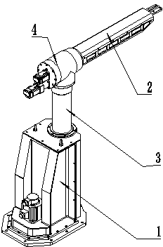
[0026] Example 1 :like Figure 1-9 As shown, a cylindrical coordinate robot includes a Z-axis 1 that can move in the Z-direction, an X-axis 2 that can move in the X-direction, a rotation axis 3 that can rotate in the Z-direction, and a flip axis that can rotate in the X-direction 4; wherein, the rotation axis 3 is arranged on the Z axis 1 , the inversion axis 4 is arranged on the rotation axis 3 , and the X axis 2 is arranged on the inversion axis 4 .

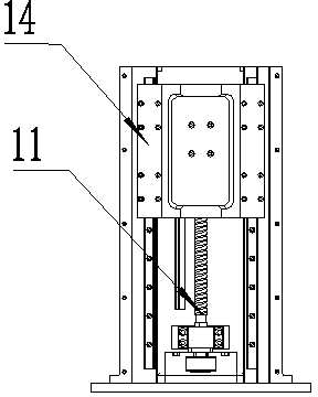
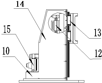
[0027] The Z-axis 1 includes a base 10 on which a lead screw transmission device 11 is arranged along the Z direction, and the lead screw transmission device 11 includes a nut seat 12 on which Z is arranged. The shaft lifting seat 13 is provided with a casing 14 fixed on the base 10 outside the screw drive 11 , and an AC for driving the screw drive 11 is also provided on the base 10 Servo motor 15.

[0028] The rotating shaft 3 includes an AC servo motor 30, a planetary reducer 31 and a transmission shaft 32 arranged along ...


PUM


Abstract

The invention discloses a cylindrical coordinate robot which comprises a Z shaft (1), an X shaft (2), a rotating shaft (3) and a turning shaft (4), wherein the Z shaft (1) can move in the Z direction, and the X shaft (2) can move in the X direction; the rotating shaft (3) can rotate in the Z direction, and the turning shaft (4) can rotate in the X direction; the rotating shaft (3) is arranged on the Z shaft (1), the turning shaft (4) is arranged on the rotating shaft (3), and the X shaft (2) is arranged on the turning shaft (4). The robot can realize turning of materials and also has the advantages of being simple and compact in structure, great in stability and rigidity and small in occupied area.

Description

technical field [0001] The invention relates to a cylindrical coordinate robot. Background technique [0002] In today's processing and manufacturing industry, the loading and unloading of the production line of many factories is still done manually, which is labor-intensive and low in production efficiency. In order to improve work efficiency, reduce labor costs, and adapt to modern automated production, a cylindrical coordinate robot is designed to replace manual loading and unloading. to increase labor productivity. The existing cylindrical coordinate robot mainly uses the screw transmission device to realize the translation of the material and the multi-axis rotation mechanism to realize the rotation of the material, and there is no mechanism to realize the material's own turnover. Finish. Moreover, the structure of the multi-axis rotating mechanism adopted by the existing cylindrical coordinate robot is too complicated, and the overall rigidity of the structure is wea...

Claims


Application Information

Patent Timeline
Patent Type & Authority Applications(China)
IPC IPC(8): B25J9/04
Inventor 于今杨昌林吴海燕龙海洋
Owner CHONGQING LANGZHENG TECH
Why Eureka
Try Eureka