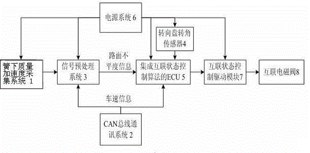
[0017] Such as figure 1 As shown, the horizontally interconnected air suspension interconnection state control system of the present invention consists of an unsprung mass acceleration acquisition system 1, a CAN bus communication system 2, an information preprocessing system 3, a steering wheel angle sensor 4, an ECU 5 integrated with an interconnection state control algorithm, and an interconnection State control drive module 7, interconnected solenoid valve 8 and power supply system 6.
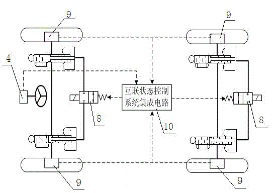
[0018] Combine figure 1 with figure 2 The unsprung mass acceleration acquisition system 1 is composed of several unsprung mass acceleration sensors 9 and sensor signal transmission lines, wherein the unsprung mass acceleration sensor 9 is arranged at each unsprung mass (such as a wheel hub). For example for figure 2 For the four-wheeled vehicle shown, four unsprung mass acceleration sensors 9 need to be arranged, and each unsprung mass acceleration sensor 9 transmits an acceleration signal to the signal preprocessing system 3 through a signal transmission line. The CAN bus communication system 2, the information preprocessing system 3, the ECU5 that integrates the interconnected state control algorithm, the interconnected state control drive module 7, and the power supply system 6 are integrated in the hardware to integrate figure 2 The interconnection status in the control system integrated circuit 10.
[0019] The CAN bus communication system 2 is used for communication between the air suspension interconnection state control system and the vehicle CAN (controller area network) bus, so as to obtain vehicle speed information from the vehicle CAN bus. The output of the CAN bus communication system 2 is respectively connected to the input of the information preprocessing system 3 and the input of ECU5, and the vehicle speed information is respectively transmitted to the information preprocessing system 3 and ECU5 through the signal transmission line, which is necessary for identifying the road unevenness and judging the ideal interconnection state information.
[0020] The input of the signal preprocessing system 3 is also connected to the output of the unsprung mass acceleration acquisition system 1 for preprocessing the collected vehicle speed information and unsprung mass acceleration information, and has the functions of signal amplification, filtering, and road roughness calculation. There are many road surface unevenness identification methods. In the present invention, the road surface unevenness is identified based on the information of unsprung mass acceleration and driving speed. The specific identification method is recorded in the application number 201410581629. "On-line recognition system and method", I won’t repeat it here. The vehicle speed information is obtained by the CAN bus communication system 2, and this information will also be used by the ECU 5 to determine driving conditions. Therefore, this structure can also realize the concept of "structure sharing, information fusion, and control coordination" advocated by modern system engineering. The unsprung mass acceleration acquisition system 1 and the CAN bus communication system 2 are signal input terminals, which respectively provide unsprung mass acceleration information and vehicle speed information. After the signal preprocessing system 3 completes the signal processing, it provides road roughness information to the ECU 5 through the signal transmission line.
[0021] The steering wheel angle sensor 4 is installed at the position of the vehicle steering wheel to collect information about the vehicle steering wheel angle. The output of the steering wheel angle sensor 4 is connected to the input of the ECU 5 through a signal transmission line, and the information is provided to the ECU 5.
[0022] ECU5 integrates an interconnected state control algorithm. The algorithm takes three information of vehicle speed average information, road unevenness information and steering wheel angle as input, and interconnected state variables as output. Among them, the two input parameters of vehicle speed average information and road unevenness information are provided by the information preprocessing system 3 and updated every few seconds; to ensure driving safety, the steering wheel angle information needs to be updated in real time, so the CAN bus communication system 2 directly provides . Interconnection state variables include "interconnection state on" and "interconnection state off", represented by high level and low level respectively.
[0023] The interconnected state control drive module 7 and the interconnected solenoid valve 8 are collectively called an interconnected state control execution system. The input of ECU 5 is connected to the interconnection state control drive module 7 through a signal transmission line, and the output of the interconnection state control drive module 7 is connected to an interconnection solenoid valve 8 through a control line. The interconnection solenoid valve 8 is located between the interconnection pipelines connecting the left and right air springs. After determining the interconnection state according to the three input parameters of vehicle speed information, road unevenness information and steering wheel angle, ECU5 provides a high-level or low-level command signal to the interconnection state control execution system. For four-wheeled vehicles, the spatial arrangement is as figure 2 Shown. The interconnection state control driving module 7 receives the interconnection state variable information output by the ECU 5 integrated with the interconnection state control algorithm. If the received variable information is high, the interconnected solenoid valve 8 is energized and turned on; if the received variable information is low, the interconnected solenoid valve 8 is powered off and turned off.
[0024] The power supply system 6 supplies power to the unsprung mass acceleration acquisition system 1, the signal preprocessing system 3, the steering wheel angle sensor 4, the ECU 5, and the interconnection state control driving module 7 respectively through the power cord.
[0025] The horizontal interconnection of the air suspension can improve the ride comfort of the vehicle, which is particularly obvious on bad roads. When the vehicle is turning, the body rolls, and the exchange of gas between the air springs of the Unicom will further aggravate the roll effect, especially when the vehicle is traveling at a high speed. Therefore, the interconnection air suspension control should determine whether the interconnection state is turned on or off according to the quality of the road surface, the turning and non-turning conditions of the vehicle, and it should meet the basic control requirements shown in Table 1 below:
[0026] Table 1
[0027] ,
[0028] Turn on the interconnection state when the vehicle is driving on a bad road, and turn off the interconnection state when the vehicle is turning. When the vehicle is in or not at the same time, the interconnection state is opened and closed by the speed of the vehicle: it is turned on when the vehicle speed is low, and the vehicle speed is higher. When closed.
[0029] According to the basic control requirements in Table 1, the basic control algorithm of the interconnection state control of the transverse interconnection air suspension is determined. The vehicle roll characteristics are simultaneously related to the vehicle's handling stability and driving comfort. Therefore, the present invention designs a control algorithm that aims at stabilizing the body posture. The calibration method of specific parameters in the control algorithm is as follows image 3 As shown, the specific steps are as follows:
[0030] Step 1: Random road driving test or simulation of the sample car. Since different models have different dynamic characteristics, the trigger conditions for turning on or off the interconnection state are naturally different. Therefore, it is necessary to first control some important parameters in the control algorithm for the parameters of a model model and the dynamic characteristics of a model model. Perform calibration. First, install the interconnected state control system involved in the present invention in the prototype of the vehicle to be calibrated, and conduct road tests under different working conditions, different levels of roads, and different interconnected states. The simulation or test variables include road conditions and two types of steering. There are two interconnected states of the wheel angle, interconnected and non-interconnected, and driving speed. Collect information about body roll angle changes in simulation or test. When the steady-state steering road test is carried out under the road grades of A, B, C, D, and E, if the test conditions are insufficient, simulation can also be used. The test or simulation condition variables include road conditions, two steering wheel angles, two interconnected and non-interconnected states, and driving speed. Use the body inclination sensor to collect the information of the body roll angle in simulation or test. The two steering wheel angles respectively represent the steering wheel angles of turning conditions and non-turning conditions. The steering wheel angle of the non-turning conditions is about one-tenth of the turning angle of the turning conditions and cannot be zero. In the present invention, the vehicle body inclination sensor is only used for parameter calibration of the control algorithm, and is not necessary for the implementation of interconnected control during the actual driving process, so it is not included in the interconnected state control system hardware involved in the present invention.
[0031] Step 2: Signal analysis and tabulation. After filtering the car body roll angle information with the signal preprocessing system 3, the root mean square value of the car body roll angle during the steady-state steering test is calculated, and the simulation or test results under various working conditions are made Table to compare the rms value of the body roll angle in the connected and non-connected state. For example, if the root mean square value of the body roll angle in the connected state is less than the non-connected state, it means that the connected state should be turned on under this working condition. Otherwise, the interconnection status should be closed.
[0032] Table 2 below shows the root mean square value of the body roll angle corresponding to different road conditions, driving speed (unit: km/h), and interconnection state of a prototype vehicle under non-turning conditions (refers to the turning angle of the vehicle body relative to the ground, and Non-relatively unsprung mass rotation angle). The thick black line at the upper right represents the driving condition where the interconnection state is turned on better than the interconnection state is closed, and the thick black line at the bottom left represents the driving condition where the interconnection state is off is better than the interconnection state is turned on.
[0033] Table 3 below shows the root mean square value of the body roll angle corresponding to different road conditions, driving speeds, and interconnection conditions under the turning conditions of a prototype car of a certain model (refers to the turning angle of the vehicle body relative to the ground, not the relative unsprung mass. ). The thick black line at the upper right represents the driving condition where the interconnection state is turned on better than the interconnection state is closed, and the thick black line at the bottom left represents the driving condition where the interconnection state is off is better than the interconnection state is turned on.
[0034] According to Table 2 and Table 3, a clear and intuitive comparison can be obtained to obtain an ideal interconnection state under various working conditions.
[0035]
[0036] Table 2 Non-turning conditions
[0037] ;
[0038] Table 3 Turning conditions
[0039] .
[0040] Step 3: Formation and writing of control algorithm. The laws reflected in Tables 2 and 3 are summarized in a functional language according to the basic control requirements of the interconnected state control shown in Table 1, and the interconnected state control algorithm can be formed, that is, the control algorithm calibration for the vehicle type is completed. The control algorithm is written into ECU5 to form an interconnected state control center that can be used by users to implement control in an interconnected state, and improve the driving comfort of the vehicle while ensuring driving safety.
[0041] E.g, Figure 4 It is the control algorithm relationship diagram that summarizes the results shown in Table 2 and Table 3. This algorithm can be expressed in functional language:
[0042] When the driving condition is in a non-turning condition, the data in Table 2 is linearly fitted as:
[0043] (1)
[0044] y is the driving speed and x is the coefficient of road roughness;
[0045] When the driving condition is in a turning condition, the data in Table 3 is linearly fitted as:
[0046] (2)
[0047] Draw the functional relationship expressed by equation (1) and equation (2) as a graph, then we get Figure 4. Figure 4 in, Figure 4 The abscissa is the road surface roughness coefficient, and the ordinate is the driving speed. The longer gray band M is drawn according to formula (1) and the shorter gray band N is drawn according to formula (2).
[0048] Figure 4 It is the graphical expression of the control sentence of the interconnection state written into ECU5. ECU5 can judge the current driving condition according to the road information and driving speed information provided by the information preprocessing system 3 and CAN bus communication system 2. Figure 4 In which position. If the current driving condition is at the upper left side of the longer gray zone M, the interconnection status is closed regardless of whether the current vehicle is in a turning condition; if it is in the longer gray zone M, if the current driving condition is in a turning condition, close the interconnection If it is in a non-turning condition, keep the current interconnection status; if it is between two gray zones, if it is currently in a turning condition, turn off the interconnection status; if it is in a non-turning condition, turn on the interconnection status; In the short gray zone N, if you are currently in a turning condition, keep the current interconnection status, if you are in a non-turning condition, turn on the interconnection status; if it is at the lower right of the shorter gray zone N, regardless of whether the current vehicle is in a turning condition , Are all turned on the interconnection state.
[0049] After writing the control relationship into ECU5, see Figure 5 , The implementation method of interconnection control during driving is as follows:
[0050] Step 1: During the driving process, real-time monitoring and collecting road unevenness information, vehicle speed information and steering wheel angle information. The unsprung mass acceleration acquisition system 1 is used to monitor the unsprung mass acceleration information in real time, the CAN bus communication system 2 provides vehicle speed information, and the steering wheel angle sensor 4 provides the steering wheel angle information. The unsprung mass acceleration information is transmitted to the information preprocessing system 3 in real time, the steering wheel angle information is transmitted to the ECU 5 in real time without preprocessing, and the vehicle speed information is transmitted to the information preprocessing system 3 and ECU5 at the same time.
[0051] Step 2: The information preprocessing system 3 calculates the road unevenness information according to the unsprung mass acceleration information and the vehicle speed information provided by the unsprung mass acceleration acquisition system 1 and the CAN bus communication system 2, and sends it to the ECU5.
[0052] Step 3: The information preprocessing system 3 filters the collected road surface unevenness information and vehicle speed information, and sends the average value of road surface unevenness and vehicle speed within a few seconds to ECU 5 every few seconds, while the steering wheel angle information does not pass through the information. The preprocessing system 3 is transmitted to the ECU 5 in real time. ECU5 compares the current road unevenness information (updated every few seconds), vehicle speed information (updated every few seconds) and steering wheel angle (real-time update) with the control algorithm, and judges the current system according to the interconnection state control algorithm Ideal interconnection state under working conditions. If the ideal interconnection state is "interconnected", the ECU 5 outputs a high-level signal to the interconnection state control execution system; if the ideal interconnection state is "non-interconnected", it outputs a low-level signal. The interconnection status control driving module 7 in the interconnection status control execution system receives this signal. If it is high, it supplies power to the interconnection solenoid valve 8, controls the interconnection solenoid valve 8 to open, and the left and right air springs are interconnected; if it is low, then No power is supplied to the interconnection solenoid valve 8, the control interconnection solenoid valve 8 is closed, and the left and right air springs interrupt the interconnection.