
Rotary wheel assembly

A technology of rotating wheels and components, applied in the field of mechanical processing, can solve the problems of difficult control of feeding speed, low production efficiency, inability to adapt to different sizes of rod materials, etc., and achieve the effect of convenient installation and simple structure

Active Publication Date: 2015-03-25
江苏兴业铝材有限公司
View PDF9 Cites 2 Cited by
  • Summary
  • Abstract
  • Description
  • Claims
  • Application Information

AI Technical Summary

Problems solved by technology

[0002] The processing of traditional rod-shaped parts, such as the processing of the shock absorber rod, needs to grind the workpiece on a centerless grinder. At present, most of the rods are fed into the centerless grinder by manual feeding. The operator needs to stand in front of the equipment without moving. Stop feeding, using this feeding method, not only the labor intensity is high, the production efficiency is low, the labor cost is high, but also the feeding speed is difficult to control, which makes the processed products poor in consistency and affects the product qualification rate. When cutting, the coolant will volatilize and produce water mist with peculiar smell. The operator is close to the equipment and has a strong pungent sensation. The chest and cuffs of the clothes will be relatively wet. Workers have been in such an environment for a long time, and there are certain safety hazards. The traditional The transmission mechanism cannot guarantee a good feeding rate, and cannot adapt to the transmission of rod materials of different sizes, the efficiency is low, and the labor intensity is high

Method used


Image

  • Rotary wheel assembly
  • Rotary wheel assembly
  • Rotary wheel assembly

Examples


Embodiment Construction

[0029] The implementation of the present invention will be illustrated by specific specific examples below, and those skilled in the art can easily understand other advantages and effects of the present invention from the contents disclosed in this specification.

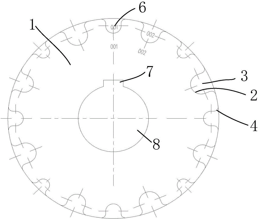
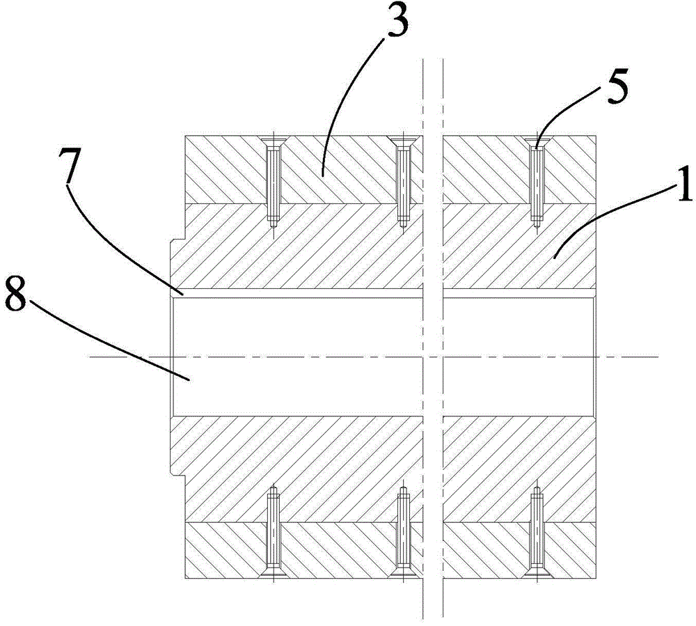
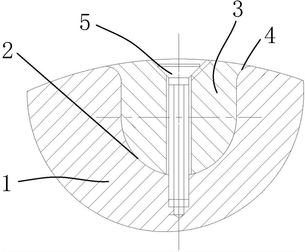
[0030] Such as Figure 1 to Figure 3 As shown, the present invention provides a rotating wheel assembly, including a rotating wheel main body 1, a groove 2 is provided on the outer surface of the rotating wheel main body 1 along the axial direction, and a groove 3 is detachably installed in the groove 2 to cooperate with the groove 2. The clip 3, the clip 3 and the groove bottom of the groove 2 are provided with installation holes correspondingly, the clip 3 and the rotating wheel main body 1 are connected by the screws 4 pierced in the installation holes, and the screws 4 are buried in the clip 3, And the clamping strip 3 is flush with or lower than the outer circular surface of the rotating wheel main body 1 . Th...


PUM

PropertyMeasurementUnit
Radiusaaaaaaaaaa

Abstract

The invention provides a rotary wheel assembly which comprises a rotary wheel body. At least one set of grooves is formed in the outer circle face of the rotary wheel body in the axial direction, clamping bars matched with the grooves are detachably arranged in the grooves, and the clamping bars are flush with or lower than the outer circle face of the rotary wheel body. According to the rotary wheel assembly, rod-shaped workpieces can be conveyed to machining equipment to be machined fast and orderly through an automatic feeding device with the rotary wheel assembly, the rotary wheel assembly is suitable for conveying the rod-shaped workpieces of different dimensions, the structure is simple, and mounting is convenient.

Description

technical field [0001] The invention relates to the technical field of machining, in particular to a rotating wheel assembly. Background technique [0002] The processing of traditional rod-shaped parts, such as the processing of the shock absorber rod, needs to grind the workpiece on a centerless grinder. At present, most of the rods are fed into the centerless grinder by manual feeding. The operator needs to stand in front of the equipment without moving. Stop feeding, using this feeding method, not only the labor intensity is high, the production efficiency is low, the labor cost is high, but also the feeding speed is difficult to control, which makes the processed products poor in consistency and affects the product qualification rate. When cutting, the coolant will volatilize and produce water mist with peculiar smell. The operator is close to the equipment and has a strong pungent sensation. The chest and cuffs of the clothes will be damp. Workers have been in such an ...

Claims


Application Information

Patent Timeline
IPC IPC(8): B65G29/00
CPCB65G29/00
Inventor 张杰田祥云黄强翁长江周明元杨志明李耀勇
Owner 江苏兴业铝材有限公司
Learn More