Eureka AIR delivers breakthrough ideas for toughest innovation challenges, trusted by R&D personnel around the world.

A closed-top suction type fixed bed gasifier waste heat recovery device

A technology of waste heat recovery device and fixed bed gasifier, which is applied in chemical industry, manufacture of combustible gas, climate sustainability, etc. It can solve the problems of difficult heat energy recovery, high requirements, fast corrosion, etc., and achieve the purpose of suppressing low temperature Effects of synthesis reaction, load reduction, and thermal efficiency improvement

Inactive Publication Date: 2017-02-01
CHINESE RES ACAD OF ENVIRONMENTAL SCI
View PDF7 Cites 0 Cited by
  • Summary
  • Abstract
  • Description
  • Claims
  • Application Information

AI Technical Summary

Problems solved by technology

However, there are still many problems in the direct incineration of garbage, such as the acid gas produced by the incineration of organic matter in garbage components, highly toxic chlorine-containing polymer compounds, and fly ash containing Hg and Pb, etc.
In addition, incineration places high demands on equipment and corrodes quickly
The high-temperature flue gas from incineration has high utilization value, but its heat recovery is not easy to achieve

Method used


Image

  • A closed-top suction type fixed bed gasifier waste heat recovery device
  • A closed-top suction type fixed bed gasifier waste heat recovery device
  • A closed-top suction type fixed bed gasifier waste heat recovery device

Examples


Embodiment Construction

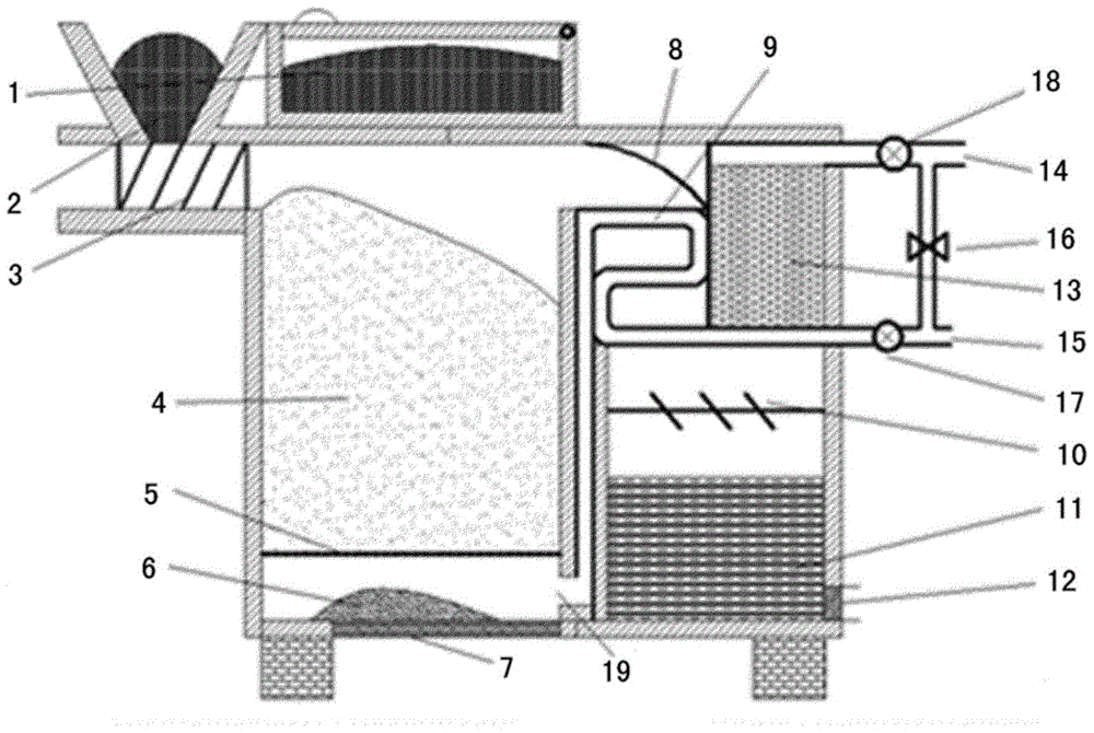
[0028] The waste heat recovery device of the airtight updraft fixed-bed gasifier of the present invention is a small device, which is especially suitable for pyrolysis treatment of domestic garbage in villages and towns. The closed type of the device is beneficial to control the intake of air and the temperature of the gasification medium, which not only makes the pyrolysis working condition easy to control, but also improves the thermal efficiency of the furnace body.

[0029] Technical solution of the present invention is based on following principle:

[0030] According to the research, the outlet temperature of the updraft fixed bed pyrolysis gas is about 500°C. According to the static pressure recovery method, the pyrolysis gas first passes through the gas deflector, and then passes through the heat exchanger at a constant speed. During the heat exchange process, the temperature of the pyrolysis gas decreases, and the temperature of the gasification medium increases signif...


PUM


Abstract

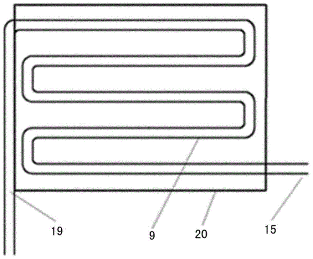
The invention provides a closed updraught type fixed bed gasification furnace waste heat recycling device. The closed updraught type fixed bed gasification furnace waste heat recycling device comprises a material storage cabin, wherein the material storage cabin is arranged at the top of a pyrolysis gasification furnace; a feeding hole is formed in the lower side of the material storage cabin; the feeding opening corresponds to a spiral feeding device and is used for conveying materials into a pyrolysis gasification chamber of the pyrolysis gasification furnace; a fire grate and an ash discharging opening are arranged on the lower part in the pyrolysis gasification chamber; a flue gas flow guide plate is arranged on the upper part of the pyrolysis gasification chamber; pyrolysis gas of the pyrolysis gasification chamber is introduced into the waste heat recycling device to be subjected to heat exchange; after oil tar in the pyrolysis gas is cooled, the oil tar flows into an oil tar storage chamber, and the cooled pyrolysis gas after the heat exchange passes through a gas purifier and is discharged out from a pyrolysis gas outlet; an oil tar flow guide plate is horizontally arranged in the middle of the oil tar storage chamber; a discharging pipe of the waste heat recycling device is connected with an air inlet; outdoor air enters the discharging pipe of the waste heat recycling device from the air inlet and is subjected to the heat exchange with the pyrolysis gas; and the air subjected to the heat exchange is used for providing a gasification medium for the pyrolysis gasification chamber through an air outlet; and after the gasification medium and the materials are mixed and combusted, heat is provided for pyrolysis, gasification and drying in the furnace.

Description

technical field [0001] The invention relates to a device for domestic garbage pyrolysis gasification and waste heat recovery. Background technique [0002] The amount of domestic waste in rural areas in my country is close to more than 4 billion tons a year, and only 26% of the administrative villages in the country have garbage collection points, and hundreds of millions of tons of rural domestic waste are discarded without any treatment every year. A large amount of domestic garbage is discarded or stacked in the open air without order, causing serious pollution to the environment, not only occupying land, destroying the landscape, but also spreading diseases, seriously polluting the water environment, soil and air, and the living environment. Traditional waste disposal methods mainly include landfill and incineration. Landfilling will take up a lot of valuable land resources and pollute the environment (atmosphere, groundwater, etc.), so this simple treatment method is r...

Claims


Application Information

Patent Timeline
Patent Type & Authority Patents(China)
IPC IPC(8): C10J3/20C10J3/72C10J3/84
CPCC10J3/20C10J3/72C10J3/84Y02P20/10Y02P20/129
Inventor 席北斗王晓伟王鹏飞夏训峰王随林刘鸿亮
Owner CHINESE RES ACAD OF ENVIRONMENTAL SCI
Why Eureka
Eureka Blog
Learn More