Vortex tube for spinning machine

A vortex tube and spinning machine technology, applied in the field of vortex tube, can solve the problems of high air consumption rate and power consumption, affecting the spinning speed, and the gap cannot be too large, so as to save energy consumption, improve spinning quality and Efficiency, friction reduction effect

Inactive Publication Date: 2015-03-25
SUZHOU CITY WUZHONG DISTRICT GUOXIANG XUYU WOOLENSWEATER PROCESSING PLANT
View PDF9 Cites 1 Cited by
  • Summary
  • Abstract
  • Description
  • Claims
  • Application Information

AI Technical Summary

Problems solved by technology

[0002] Air-jet vortex spinning is a new spinning technology. During the spinning process or when the yarn is broken, it is inevitable that fibers will remain in the vortex chamber, which will affect the textile quality and spinning efficiency. Usually, it is connected at the end of the vortex tube. Negative pressure chamber, the residue is sucked away by negative pressure to clean the vortex chamber, but because the gap between the yarn drawing tube and the inner wall of the vortex tube should not be too large, the residual fiber is easy to block the yarn drawing tube when it is sucked by negative pressure In the gap between the vortex tube and the inner wall of the vortex tube, there are multiple airflows in the vortex tube during the spinning process, which will cause a large air consumption rate and power consumption, which will affect the spinning speed and low spinning efficiency

Method used


Image

  • Vortex tube for spinning machine

Examples


Embodiment Construction

[0010] The present invention is described below in conjunction with accompanying drawing.

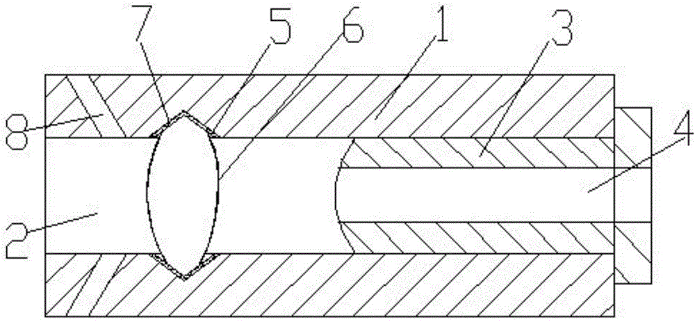
[0011] The vortex tube for spinning machine of the present invention comprises a tube body 1 provided with a hollow cavity 2, one end of the tube body is provided with a plug 3; The yarn guide hole 5, the hollow inner cavity wall is provided with a V-shaped groove structure 5; the V-shaped groove structure 5 is provided with a fiber ring 6; on the V-shaped groove structure 5 and the fiber ring 6 is provided with flannelette tissue 7 at the junction; and an inclined air supply hole 8 is provided on the wall of the hollow inner cavity near the end opposite to the end where the plug 3 is provided. The scheme of the present invention has an inclined air supply hole 8 on the hollow inner cavity wall of the pipe body 1, which can increase the effective air flow in the pipe body, improve the bearing capacity of the fiber ring, increase the rotational speed of the fiber ring, thereby improving ...


PUM


Abstract

The invention discloses a vortex tube for a spinning machine. The vortex tube comprises a tube body with an inner cavity, a plug is arranged at one end of the tube body and provided with a yarn guide hole in communication with the inner cavity, a V-shaped groove structure is arranged on a circle of the wall of the inner cavity, a fiber ring is arranged in the V-shaped groove structure, flannelette structures are arranged at the joints between the V-shaped groove structure and the fiber ring, and a tilting air supplement hole is formed in the wall, close to the end opposite to the end where the plug is arranged, of the inner cavity. According to the scheme, the tilting air supplement hole is formed in the wall of the inner cavity of the tube body, so effective air flow in the tube body can be increased, the capacity to bear the fiber ring is enhanced, the rotation speed of the fiber ring is increased, and therefore twisting efficiency is improved, energy consumption is reduced, the structural design of the flannelette structures reduces friction of the fiber ring and prolongs the service life of the fiber ring, and spinning quality and spinning efficiency are improved.

Description

technical field [0001] The invention relates to a vortex tube, in particular to a vortex tube for a spinning machine. Background technique [0002] Air-jet vortex spinning is a new spinning technology. During the spinning process or when the yarn is broken, it is inevitable that fibers will remain in the vortex chamber, which will affect the textile quality and spinning efficiency. Usually, it is connected at the end of the vortex tube. Negative pressure chamber, the residue is sucked away by negative pressure to clean the vortex chamber, but because the gap between the yarn drawing tube and the inner wall of the vortex tube should not be too large, the residual fiber is easy to block the yarn drawing tube when it is sucked by negative pressure In the gap between the vortex tube and the inner wall of the vortex tube, there are multiple airflows in the vortex tube during the spinning process, which will cause a large air consumption rate and power consumption, which will affe...

Claims


Application Information

Patent Timeline
Patent Type & Authority Applications(China)
IPC IPC(8): D01H4/02
CPCD01H4/02
Inventor 唐志宏
Owner SUZHOU CITY WUZHONG DISTRICT GUOXIANG XUYU WOOLENSWEATER PROCESSING PLANT
Why Eureka
Try Eureka