Differential pressure anti-evacuation mortar pump

A mortar pump, differential pressure technology, applied in the field of pressure differential anti-evacuation mortar pump, can solve the problems of no raw material, mortar pump idling, uncertain pulp supply, etc.

Active Publication Date: 2016-08-17
TONGLIAO SILICA SAND IND
View PDF8 Cites 6 Cited by
  • Summary
  • Abstract
  • Description
  • Claims
  • Application Information

AI Technical Summary

Problems solved by technology

However, the supply of upstream pulp is very uncertain, sometimes more and sometimes less, and the operating capacity of the mortar pump must be calculated according to the upper limit. When the pulp is low or interrupted, the mortar pump will suck in air. When the amount of air is large and cannot be discharged in time , the slurry flow will be interrupted, and the mortar pump will appear idling, causing pumping failure
If this failure cannot be detected and eliminated in time, the upstream slurry will overflow the mortar tank, and there will be no raw materials in the next process.
However, to eliminate the evacuation failure requires shutdown processing, or even stop the supply of ore pulp and even the operation of the whole line, which is very difficult to deal with and cause losses. Therefore, solving the evacuation failure has become a difficult problem in the operation of the mortar pump.

Method used


Image

  • Differential pressure anti-evacuation mortar pump
  • Differential pressure anti-evacuation mortar pump
  • Differential pressure anti-evacuation mortar pump

Examples


Embodiment Construction
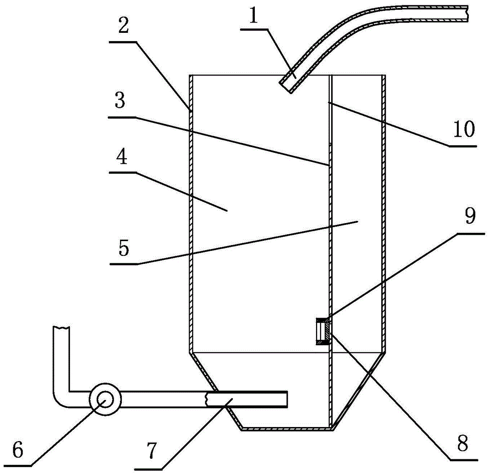
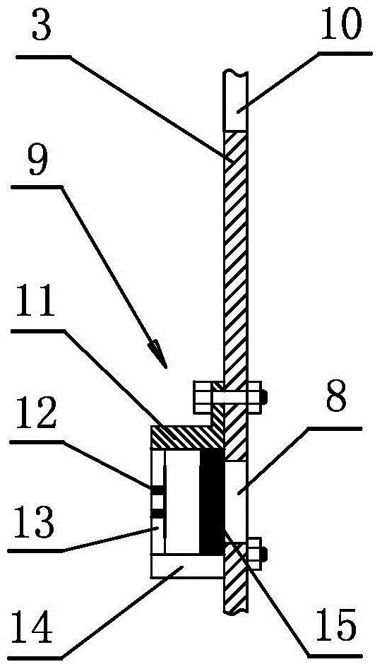
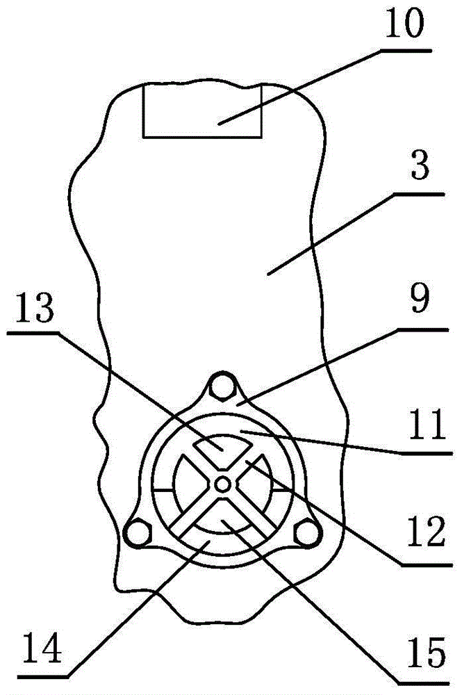
[0026] The general idea of ​​the present invention is: the mortar tank 2 is divided into two cavities, and a differential pressure valve is arranged between them. When the mortar level in one cavity is too low, the differential pressure valve is opened and the mortar in the other cavity is put in to prevent the mortar pump from being evacuated. Three embodiments are introduced below around this idea.

[0027] The first embodiment: as figure 1 As shown, this differential pressure type anti-evacuation mortar pump has a main body of a mortar tank 2, the top of the mortar tank 2 is opposite to the outlet of the slurry pipe 1, and a mortar pump 6 is arranged below the mortar tank 2, and the inlet of the mortar pump 6 7. In the lower part of the mortar tank 2, the characteristics are: the mortar tank 2 is provided with a partition 3, which divides the inner space of the tank into two parts, the main cavity 4 and the auxiliary cavity 5, and the upper part of the partition 3 has a ga...


PUM


Abstract

The invention relates to a silica sand producing device, namely a differential pressure type evacuation preventing mortar pump. The differential pressure type evacuation preventing mortar pump comprises a mortar tank (2) and a mortar pump body (6), and the inlet of the mortar pump body (6) is located at the lower portion in the mortar tank (2). The differential pressure type evacuation preventing mortar pump is characterized in that a partition plate (3) is arranged in the mortar tank (2) and divides the space in the tank into a main cavity (4) and an auxiliary cavity (5), a notch (10) is formed in the upper portion of the partition plate (3), a water draining hole (8) is formed in the lower portion of the partition plate (3), a differential pressure valve (9) is installed on the part, on one side of the water draining hole (8) and the main cavity (4), of the partition plate (3), the differential pressure valve (9) is provided with a tubular sliding sleeve (11), an end cover (12) is arranged at the outer end of the sliding sleeve (11), a water draining port (14) is formed in the lower side wall of the sliding sleeve (11), a piston disk (15) is arranged in the sliding sleeve (11), and the inner side face of the piston disk (15) and a plate face around the water draining hole (8) are closed matched faces. The differential pressure type evacuation preventing mortar pump has the advantages that in the working process of the mortar pump, a part of mortar or clean water is stored in the auxiliary cavity, when the liquid face of the mortar in the main cavity ascends to the appointed position, the differential pressure valve is automatically opened, the mortar is supplemented in the main cavity, mortar pump evacuation is avoided, and the stable work of the mortar pump is ensured.

Description

technical field [0001] The invention relates to a silica sand production equipment, namely a differential pressure type anti-evacuation mortar pump. Background technique [0002] During the washing process of silica sand, it is often necessary to use a mortar pump to pump the slurry composed of silica sand and water to the next process. This kind of mortar pump is installed on the outer lower part of the mortar tank. The inlet of the mortar pump is placed in the lower part of the mortar tank. However, the supply of upstream pulp is very uncertain, sometimes more and sometimes less, and the operating capacity of the mortar pump must be calculated according to the upper limit. When the pulp is low or interrupted, the mortar pump will suck in air. When the amount of air is large and cannot be discharged in time , the slurry flow will be interrupted, and the mortar pump will run idly, causing pumping failure. If this failure cannot be detected and eliminated in time, the upstr...

Claims


Application Information

Patent Timeline
Patent Type & Authority Patents(China)
IPC IPC(8): F04D29/00F04D15/00
CPCF04B23/025F04B49/04
Inventor 白福山李继余刘建华
Owner TONGLIAO SILICA SAND IND
Why Eureka
Try Eureka