A hydraulic pump load system that can be used for simultaneous ground test runs of two types of aero-engines
An aero-engine and load system technology, applied in mechanical equipment, fluid pressure actuating devices, servo motors, etc., can solve the problems of increasing capital and land resources, increasing engine production costs, and increasing hydraulic pump load systems, etc. resources, improving the efficiency of the test run, and the effect of stable flow
- Summary
- Abstract
- Description
- Claims
- Application Information
AI Technical Summary
Problems solved by technology
Method used
Image
Examples
Embodiment 1
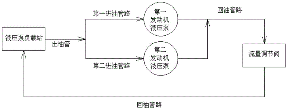
[0020] In this embodiment, the structural block diagram of the hydraulic pump load system that can be used for the ground test of two types of aero-engines is as follows: figure 1 As shown, the hydraulic schematic diagram is as follows Figure 4 As shown, it includes the hydraulic pump load station b1, and the first oil inlet pipeline that provides pressure oil for the first engine hydraulic pump and the second oil inlet pipeline that provides pressure oil for the second engine hydraulic pump are connected in parallel on the oil outlet pipe of the hydraulic pump load station. The oil inlet pipeline is provided with a flow regulating valve on the oil return pipeline of the hydraulic pump load station.
[0021] from Figure 4 It can be seen that the hydraulic pump load station b1 includes a pressure oil tank 9, which is connected with a pressurized air circuit composed of a gas cylinder 1, a pressure reducing valve 2, an air filter 3, and a needle valve 4, and the exhaust contr...
Embodiment 2
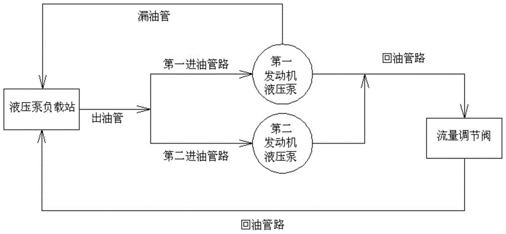
[0024] In this embodiment, the structural block diagram of the hydraulic pump load system that can be used for the ground test of two types of aero-engines is as follows: figure 2 As shown, the hydraulic schematic diagram is as follows Figure 5 shown. The difference from Embodiment 1 is that the first engine hydraulic pump b2 requires oil leakage. During the test run, the oil leakage port of the first engine hydraulic pump is connected to the oil leakage pipe joint 30 provided on the pressure oil tank 9 through a pipe fitting.
Embodiment 3
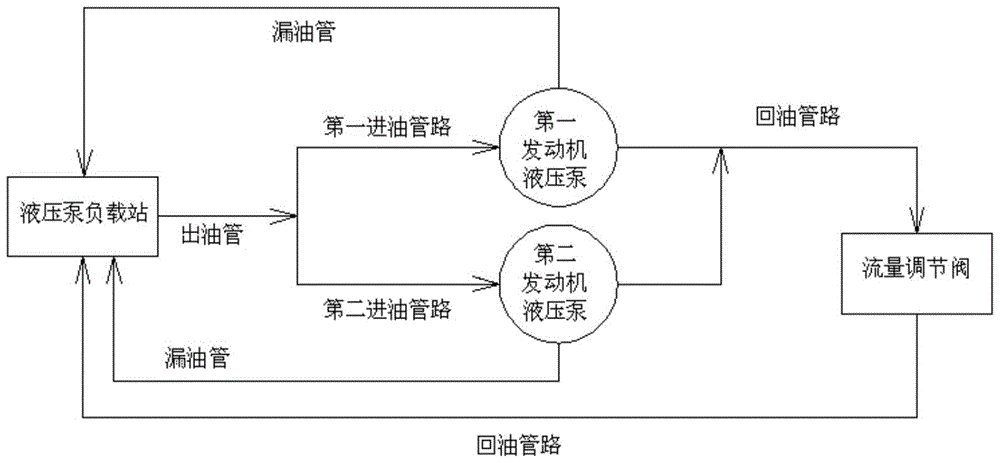
[0026] In this embodiment, the structural block diagram of the hydraulic pump load system that can be used for the ground test of two types of aero-engines is as follows: image 3 As shown, the hydraulic schematic diagram is as follows Image 6 shown. The difference from Embodiment 1 is that both the first engine hydraulic pump b2 and the second engine hydraulic pump b3 need to leak oil. During the test run, the oil leakage port of the first engine hydraulic pump and the oil leakage port of the second engine hydraulic pump respectively pass The pipe fitting is connected with the oil leakage pipe joint 30 provided with the pressure oil tank 9 .
PUM
 Abstract
Description
Claims
Application Information
 - R&D
- Intellectual Property
- Life Sciences
- Materials
- Tech Scout
- Unparalleled Data Quality
- Higher Quality Content
- 60% Fewer Hallucinations
Browse by: Latest US Patents, China's latest patents, Technical Efficacy Thesaurus, Application Domain, Technology Topic, Popular Technical Reports.
© 2025 PatSnap. All rights reserved.Legal|Privacy policy|Modern Slavery Act Transparency Statement|Sitemap|About US| Contact US: help@patsnap.com


