Evaporator integrated component

A technology of evaporators and components, applied in evaporators/condensers, refrigeration components, mechanical equipment, etc., can solve problems such as gas-liquid separation, reduce the heat transfer capacity of heat exchangers, reduce the performance of refrigeration and air-conditioning systems, and improve efficiency and energy-saving performance, reduce energy loss, and shorten the stroke

Inactive Publication Date: 2015-03-25
ZHEJIANG SANHUA AUTOMOTIVE COMPONENTS CO LTD
View PDF9 Cites 24 Cited by
  • Summary
  • Abstract
  • Description
  • Claims
  • Application Information

AI Technical Summary

Problems solved by technology

If the gas-liquid separation of the refrigerant is serious, the refrigerant that enters part of the flat tubes will be in the gas phase and the other part will be in the liquid phase. The area with too much gas-phase refrigerant will have a larger superheated area, and the area with too much liquid-phase refrigerant will Refrigerant evaporation is not completely unable to complete heat exchange, which will seriously affect the heat exchange capacity of the heat exchanger, so as to reduce the performance of the entire refrigeration and air conditioning system
[0007] In the prior art, connecting pipes are used to connect various components. In this system, the gas-liquid two-phase mixed refrigerant that has been throttled and depressurized by the throttling device cannot immediately enter the evaporator, and needs to flow through the connecting pipes to It can enter the evaporator. In this section of the journey, the gas-liquid mixed-phase refrigerant is prone to gas-liquid separation. After entering the micro-channel heat exchanger, it is easy to cause uneven distribution of the refrigerant inside the heat exchanger, thereby reducing The heat transfer capacity of the heat exchanger

Method used


Image

  • Evaporator integrated component
  • Evaporator integrated component
  • Evaporator integrated component

Examples


Embodiment Construction

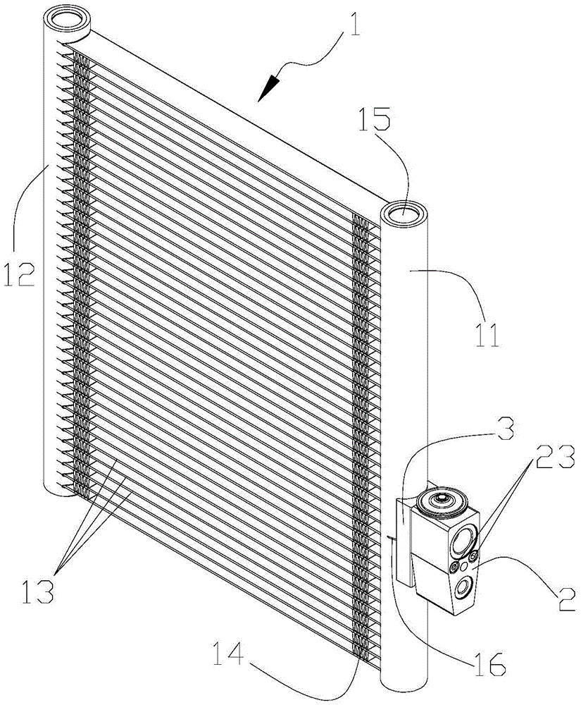
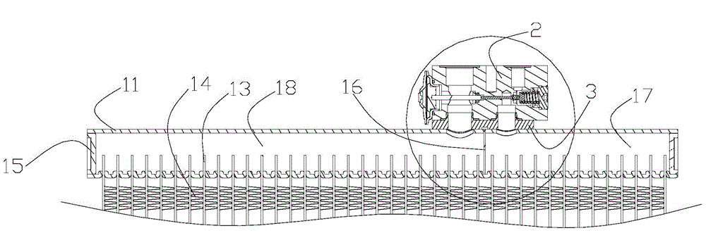
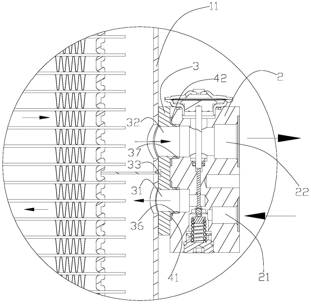
[0032] The present invention provides an evaporator integrated assembly. The evaporator integrated assembly of the present invention includes an expansion valve and a heat exchanger. The expansion valve is fixedly installed on one of the header pipes through a connecting block. In this way, the expansion valve and the heat exchanger can be realized as There is no pipeline connection between the inlet and outlet of the heat exchanger of the evaporator, and the refrigerant throttling through the expansion valve can directly flow into the evaporator, which reduces the journey of the refrigerant from the expansion valve to the evaporator, making the refrigerant It maintains the gas-liquid two-phase state very well, which is conducive to the uniform distribution of refrigerant in the evaporator, and also prevents the energy loss of refrigerant in the connecting pipeline, and has a simple structure, which can effectively improve the efficiency of the air conditioning system and energ...


PUM


Abstract

The invention provides an evaporator integrated component. The evaporator integrated component comprises a heat exchanger, connecting blocks and a thermal expansion valve, wherein the connecting block is fixed and mounted on a collecting main of the heat exchanger through welding; the thermal expansion valve is fixed and mounted on the connecting block through a screw; the collecting main is provided with a spacing plate for sealing and dividing the collecting main into a first cavity and a second cavity; and an inlet and an outlet of the heat exchanger are respectively positioned in the first cavity and the second cavity, and are communicated with the thermal expansion valve through the connecting blocks. The evaporator integrated component can realize no-pipeline connection between the expansion valve and the inlet and the outlet of the heat exchanger which serves as an evaporator, so that refrigerant is evenly distributed in the evaporator, and the energy loss of the refrigerant in the connecting pipelines is prevented; and the evaporator integrated component is simple in structure, and can effectively improve the efficiency of an air conditioning system and the energy saving performance.

Description

technical field [0001] The invention belongs to the technical field of refrigeration, in particular to a heat exchanger integrated assembly. Background technique [0002] At present, most air-conditioning systems have compressors, condensers, expansion valves, and evaporators. They are connected by connecting pipes to form a refrigeration cycle, so that the refrigerant can flow from the compressor to the condenser to the expansion valve to the evaporator and back to the evaporator. A path such as a compressor performs circulation flow. For the air conditioning system, the refrigerant releases heat to the outside through the condenser, and the refrigerant absorbs heat from the outside through the evaporator. [0003] In the air-conditioning system, the ratio of the cooling capacity (heating capacity) and the input power (COP value) that the air-conditioning system can achieve is usually used to measure the efficiency and energy-saving performance of the air-conditioning syst...

Claims


Application Information

Patent Timeline
Patent Type & Authority Applications(China)
IPC IPC(8): F25B39/02F25B41/06F25B41/30
CPCF25B39/02F25B2500/11F25B41/31
Inventor 不公告发明人
Owner ZHEJIANG SANHUA AUTOMOTIVE COMPONENTS CO LTD
Why Eureka
Try Eureka