
Device and method for measuring rotating speed of large rotating equipment

A technology of rotating equipment and rotating speed, which is applied in the direction of devices using electric/magnetic methods, can solve the problems of the limitation of speed measurement capability and the difficulty of meeting the precise measurement requirements of high speed and low speed at the same time, so as to avoid mechanical wear and wide Speed ​​measurement range, light weight effect

Inactive Publication Date: 2015-03-25
XI AN JIAOTONG UNIV
View PDF4 Cites 11 Cited by
  • Summary
  • Abstract
  • Description
  • Claims
  • Application Information

AI Technical Summary

Problems solved by technology

[0003] The purpose of the present invention is to provide a device and method for measuring the rotational speed of large rotating equipment combined with an electrostatic sensor and an eddy current sensor, which can solve the limitation of the full-range speed measurement capability of the existing rotational speed measuring device for large rotating equipment, and it is difficult to meet the high speed requirements at the same time. Accurate measurement requirements of rotational speed and low rotational speed

Method used


Image

  • Device and method for measuring rotating speed of large rotating equipment
  • Device and method for measuring rotating speed of large rotating equipment
  • Device and method for measuring rotating speed of large rotating equipment

Examples


Embodiment Construction

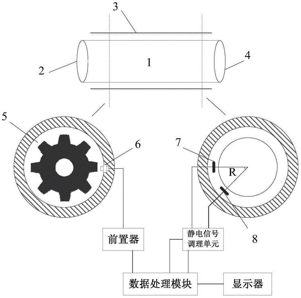
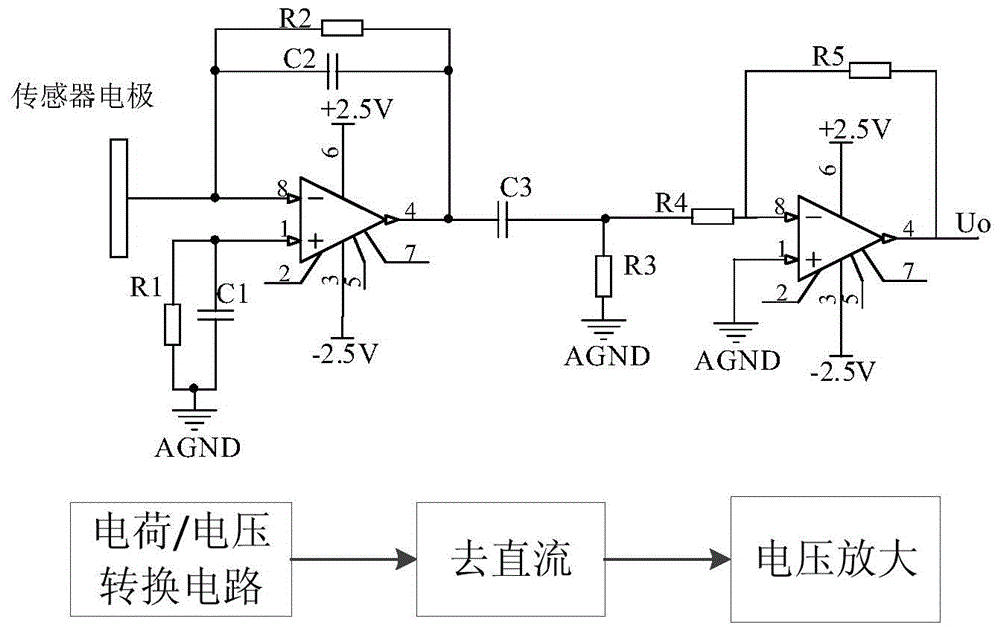
[0027] reference figure 1 , A device that uses electrostatic and eddy current sensors to measure the speed of large rotating equipment, including an eddy current sensor 6, two integrated electrostatic sensors 7, 8, and a speed measuring gear 5. Wherein, the speed measuring gear 5 is installed on the end surface 2 of the rotating shaft 1 to be measured, the eddy current sensor is fixed on the inner side of the casing relative to the flange of the speed measuring gear, and the distance between the sensor probe and the gear flange is 2mm to 5mm. The integrated electrostatic sensors 7, 8 are fixed on the inner side of the casing 3 at the periphery of the imaginary section 4 of the rotating shaft 1 to be tested. The axial distance between the imaginary section 4 and the end face 2 of the rotating shaft is at least 6cm, and the distance between the electrode of the electrostatic sensor and the rotating shaft to be tested is 2mm To 6mm. The center angle of the two integrated electros...


PUM

PropertyMeasurementUnit
Axial lengthaaaaaaaaaa
Widthaaaaaaaaaa

Abstract

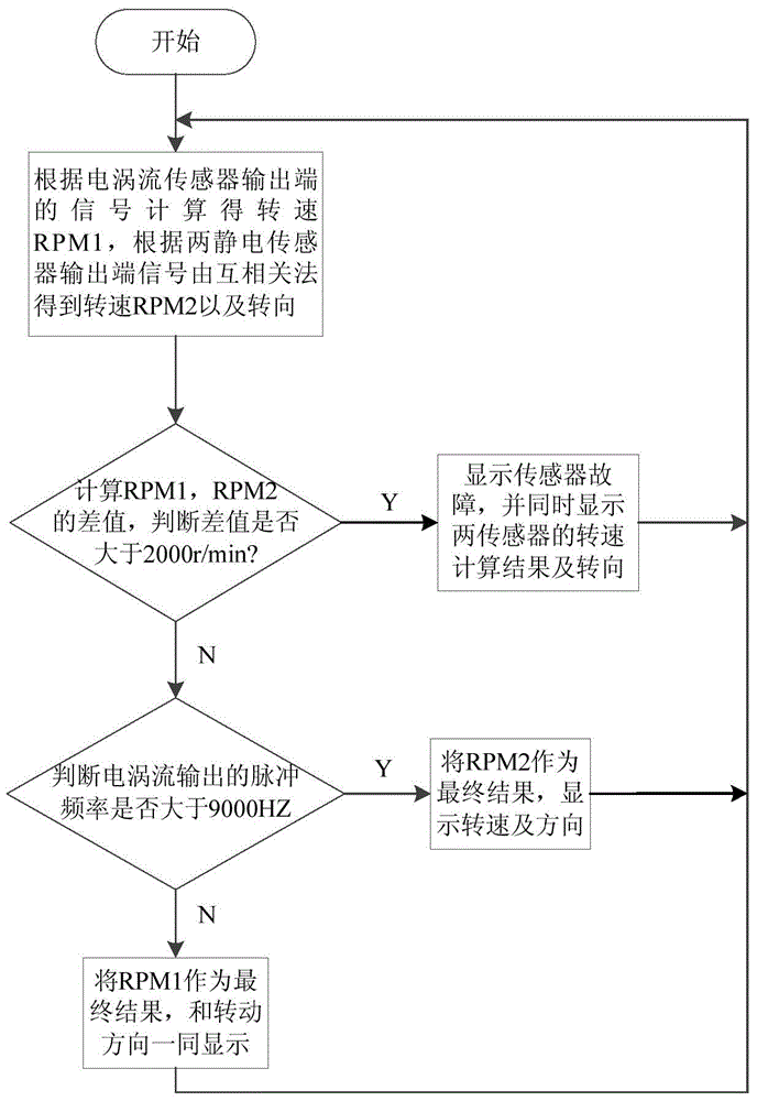
The invention discloses a device and method for measuring the rotating speed of large rotating equipment. Integrated electrostatic sensors and an eddy current sensor are adopted for measuring the rotating speed, wherein the eddy current sensor is used for sensing the rotating movement of a speed measuring gear and outputting a voltage signal, and the integrated electrostatic sensors are used for sensing an electric charge signal generated by friction between the surface of a rotating object and the air and converting the electric charge signal into a voltage signal; the two types of signals are output to a data processing module, preliminary rotating speed calculation, sensor fault judgment and rotating speed range judgment are carried out on the signals, and the accurate rotating speed of the rotating object to be detected is obtained finally and displayed on a displayer. According to the device and method, non-contact measurement is adopted, the advantage of high accuracy of measuring a high rotating speed through an electrostatic method and the advantage of high accuracy of measuring a low rotating speed through the eddy current sensor are integrated, the rotating speed can be reliably and stably measured no matter whether the large rotating equipment operates at a zero rotating speed or a low rotating speed or a high rotating speed, and meanwhile the rotating direction of a rotating shaft can be obtained and displayed.

Description

Technical field [0001] The invention relates to a rotating speed measuring device and method for large rotating equipment (such as industrial steam turbines, flue gas turbines, etc.). Background technique [0002] Rotation speed is one of the important parameters reflecting the operating conditions of rotating machinery. Rotational speed measurement accuracy, real-time measurement and reliability are the keys to ensuring the normal operation of rotating machinery. Common rotational speed measurement methods include analog measurement methods and digital measurement methods. The analog application tachogenerator is the detection element, and the signal obtained is the voltage; the digital type often uses photoelectric encoding disks, Hall elements, etc. as the detection elements to obtain Is a pulse signal. The use of photoelectric encoder disks to measure rotational speed has high requirements on the environment. If dust and oil pollution are serious, the reliability of the mea...

Claims


Application Information

Patent Timeline
IPC IPC(8): G01P3/49
Inventor 胡红利杨星月王小鑫杨帆范优飞刘骁
Owner XI AN JIAOTONG UNIV
Learn More