
Non-contact separation type unmanned aerial vehicle propeller locking device and locking method

A locking device and propeller technology, applied in the field of unmanned aerial vehicles, can solve the problems of shortening the life of the locking mechanism, increasing the structural weight of the unmanned aerial vehicle, producing mechanical friction, etc., to avoid mechanical wear, short locking time, and large locking torque. Effect

Active Publication Date: 2018-09-04
NORTHWESTERN POLYTECHNICAL UNIV
View PDF7 Cites 3 Cited by
  • Summary
  • Abstract
  • Description
  • Claims
  • Application Information

AI Technical Summary

Problems solved by technology

Contact locking is often implemented with an eccentric spring pin, the disadvantage of this method is that it will generate mechanical friction, which will reduce the life of the locking mechanism
Non-contact locking solutions often use electromagnetic methods, that is, to change the magnitude of the electromagnetic force by controlling the current. The disadvantage of this method is that it will greatly increase the structural weight of the drone.

Method used


Image

  • Non-contact separation type unmanned aerial vehicle propeller locking device and locking method
  • Non-contact separation type unmanned aerial vehicle propeller locking device and locking method
  • Non-contact separation type unmanned aerial vehicle propeller locking device and locking method

Examples


Embodiment Construction

[0037] In order to make the technical problems, technical solutions and beneficial effects solved by the present invention clearer, the present invention will be further described in detail below in conjunction with the accompanying drawings and embodiments. It should be understood that the specific embodiments described here are only used to explain the present invention, not to limit the present invention.

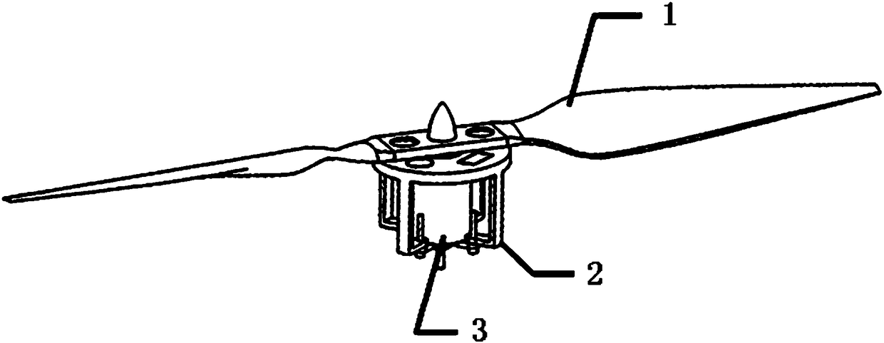
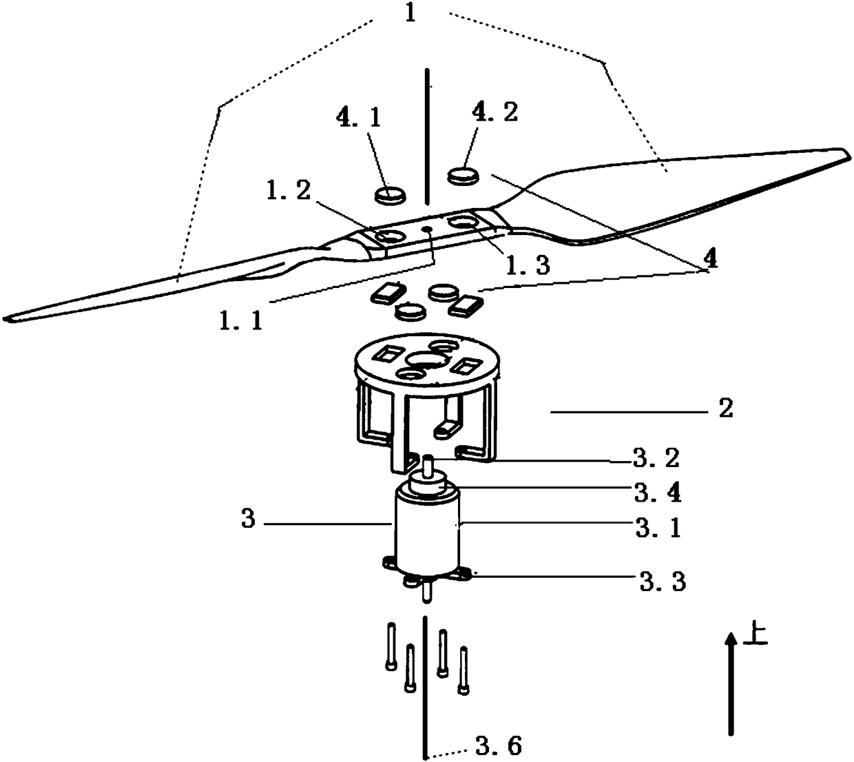
[0038] The purpose of the present invention is to provide a non-contact and separate arrangement of the UAV propeller locking device for the lift-thrust separation type (separate lift thrust) UAV, which mainly includes a propeller 1, a locking frame 2, a motor mechanism 3 and a permanent Magnet group 4; Among them, there are three groups of permanent magnet groups 4. One group of permanent magnets is arranged on the propeller, and the rest of the permanent magnets are installed on the locking frame. Multiple groups of permanent magnets are arranged according to certain ru...


PUM


Abstract

The invention provides a non-contact separation type unmanned aerial vehicle propeller locking device and a locking method. The locking device comprises a propeller, a locking frame, a motor mechanismand permanent magnet groups, wherein the permanent magnet groups comprise a first permanent magnet group, a second permanent magnet group and a third permanent magnet group; the first permanent magnet group is mounted at the root part of the propeller; the second permanent magnet group and the third permanent magnet group are mounted on a locking disk of the locking frame; a polarity arrangementmode of the second permanent magnet group is the same as that of the first permanent magnet group; the polarity arrangement mode of the third permanent magnet group is opposite to that of the first permanent magnet group. The non-contact separation type unmanned aerial vehicle propeller locking device provided by the invention has the advantages of simple structure and light weight; meanwhile, thepropeller is locked by adopting a non-contact mode, so that mechanical wear is avoided; the locking device has the advantages of large locking torque, short locking time, zero additional power loss,low fault rate, convenience in removal and maintenance and the like.

Description

technical field [0001] The invention belongs to the technical field of unmanned aerial vehicles, and in particular relates to a non-contact and separate arrangement of an unmanned aerial vehicle propeller locking device and a locking method. Background technique [0002] Lift-thrust separation (separate lift thrust) UAVs have vertical take-off and landing capabilities, and take into account both low-speed hovering capabilities and high-speed cruising performance. This type of UAV has been widely used, and its fields include aerial photography, line inspection, high-altitude environmental monitoring, etc. In order to have hovering and high-speed cruising capabilities at the same time, this type of UAV is equipped with two sets of power devices that cannot change the installation angle with the body, such as the Chinese appearance patent, publication number CN303737778S. Among them, the vertical power device installed on the wing is used to drive the propeller to rotate at lo...

Claims


Application Information

Patent Timeline
Patent Type & Authority Applications(China)
IPC IPC(8): B64C11/00B64C11/04
CPCB64C11/002B64C11/04Y02T50/60
Inventor 昌敏冯晓宇曹天时白俊强张帆
Owner NORTHWESTERN POLYTECHNICAL UNIV
Learn More