
Device for testing metal electrical resistivity change within continuous temperature range

A metal resistance and testing device technology, applied in the measurement device, measuring electrical variables, measuring resistance/reactance/impedance, etc., can solve the problems of resistivity influence, high cost, single function can not meet the test requirements, etc., to achieve precision measurement. Effect

Inactive Publication Date: 2015-03-25
SUZHOU VOCATIONAL UNIV
View PDF6 Cites 4 Cited by
  • Summary
  • Abstract
  • Description
  • Claims
  • Application Information

AI Technical Summary

Problems solved by technology

There are also four-probe or four-wire methods used in the metal resistivity test, but a large current is often required to generate a potential between the probes, and the high current often brings heating effects, which affects the resistivity test.
The traditional resistivity test or the single-chip test method, the data cannot be stored and analyzed, and the single function cannot meet the test requirements of modern rapid development, or the functions of multiple instruments are required to realize the test and measurement, and the cost is high

Method used


Image

  • Device for testing metal electrical resistivity change within continuous temperature range
  • Device for testing metal electrical resistivity change within continuous temperature range
  • Device for testing metal electrical resistivity change within continuous temperature range

Examples


Embodiment Construction

[0016] The preferred embodiments of the present invention will be described in detail below in conjunction with the accompanying drawings, so that the advantages and features of the present invention can be more easily understood by those skilled in the art, so as to define the protection scope of the present invention more clearly.

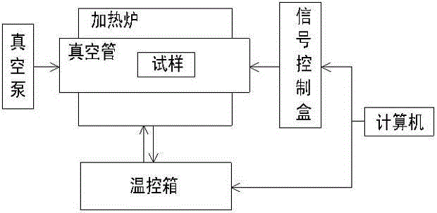
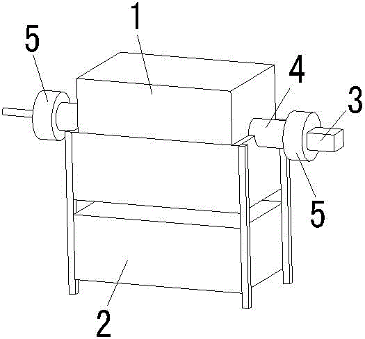
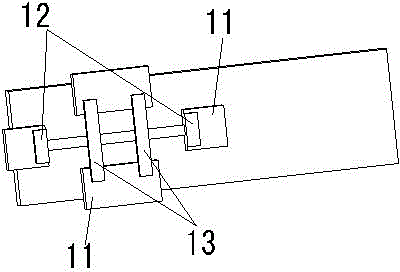
[0017] see Figure 1 to Figure 3 , the embodiment of the present invention includes:

[0018] A metal resistivity change testing device in a continuous temperature range, comprising: a ceramic terminal block 11, a heating system and a measuring system; the heating system includes an infrared heating furnace 1 and a temperature control box 2 connected to the infrared heating furnace 1; the The measurement system includes a computer and a signal control box 3 connected to the computer; the temperature control box 3 is provided with an RS485 communication port, and the temperature control box is connected to the computer through the RS485 communicat...


PUM


Abstract

The invention discloses a device for testing metal electrical resistivity change within a continuous temperature range. The device comprises a positioning mechanism, a heating system and a measurement system. The heating system comprises a heating furnace and a temperature control box connected with the heating furnace. The measurement system comprises a computer and a signal control box connected with the computer, the computer is connected with the temperature control box through a communication line, a vacuum pipe is arranged in the heating furnace, the positioning mechanism is arranged in the vacuum pipe, sealing valve bodies are arranged at the two ends of the vacuum pipe, the sealing valve body at one end of the vacuum pipe is connected with a vacuum pump, the sealing valve body at the other end of the vacuum pipe is connected with the signal control box, a temperature sensor, a current signal input clamp and a signal collecting clamp are arranged in the vacuum pipe, and the current signal input clamp and the signal collecting clamp are connected with the signal control box through wires. Through the method, the device can realize precise measurement of the metal electrical resistivity change at different heating speeds.

Description

technical field [0001] The invention relates to the fields of material analysis and electronic testing equipment, in particular to a testing device for metal resistivity change within a continuous temperature range. Background technique [0002] The conventional test method for resistivity test is the four-probe or four-wire method, which is generally tested at room temperature and is mainly used in the test of semiconductor resistivity. There are also four-probe or four-wire methods used in the metal resistivity test, but a large current is often required to generate a potential between the probes, and the high current often brings heating effects, which affects the resistivity test. The traditional resistivity test or the single-chip test method cannot store and analyze the data, and the single function cannot meet the test requirements of modern rapid development, or the functions of multiple instruments are required to realize the test and measurement, and the cost is hi...

Claims


Application Information

Patent Timeline
Patent Type & Authority Applications(China)
IPC IPC(8): G01R27/14
Inventor 张进峰
Owner SUZHOU VOCATIONAL UNIV
Learn More