
Sounding balloon for meteorological observation and air inflation method thereof

A technology for sounding balloons and meteorological observation, applied in the direction of instruments, etc., can solve the problems of loss, loss of sounding balloons, limiting the space for sounding balloons, etc., and achieve the effects of reducing lift, improving stability, and improving safety.

Inactive Publication Date: 2015-03-25
WUXI NUIST WEATHER SENSOR NETWORK TECH
View PDF5 Cites 2 Cited by
  • Summary
  • Abstract
  • Description
  • Claims
  • Application Information

AI Technical Summary

Problems solved by technology

[0007] A recyclable sounding balloon is mentioned in ZL201220732719.0. Its recovery is mainly controlled by a thin rope to control its range of motion. Although the height of the sounding balloon can be well limited by the thin rope, it also greatly limits the detection capacity of the sounding balloon. The activity space of the air balloon, and the string itself is relatively easy to break or entangle, and it is easy to lose the sounding balloon and related electronic equipment;
[0008] ZL200920044465.1 proposes a set of automatic recovery, automatic inflation, and automatic emptying of the sounding balloon, although compared with the sounding balloon in the previous patent literature, it cancels the string component and enlarges the activity space of the sounding balloon At the same time, the air pressure of some balloons and the cooperation of guiding drive equipment and sensors have improved the control ability of the sounding balloon, but the mass of the electronic equipment itself is relatively large, which will bring a certain test to the load capacity of the sounding balloon. The temperature is relatively low, so it is difficult to guarantee whether these sensors can work normally. Once the sensor fails, it will still lead to the loss of control, loss or loss of the sounding balloon, which will bring a certain maintenance burden to the observation station

Method used


Image

  • Sounding balloon for meteorological observation and air inflation method thereof

Examples


Embodiment Construction

[0035] The present invention is described in further detail now in conjunction with accompanying drawing. These drawings are all simplified schematic diagrams, which only illustrate the basic structure of the present invention in a schematic manner, so they only show the configurations related to the present invention.

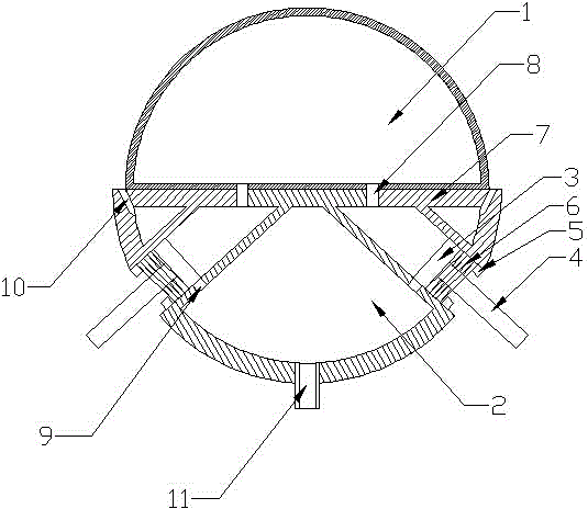
[0036] Such as figure 1 As shown, the present invention is a sounding balloon for meteorological observation, including an airbag 1, a base, and a pressure limiting mechanism, and the pressure limiting mechanism is installed on the airbag 1 through the base;

[0037] The base includes an airbag mounting seat 7 and a pressure relief cavity 2 arranged below the airbag, and the airbag 1 is fixed on the upper end of the airbag mounting seat 7;

[0038] In order to ensure the weight balance of the system, the pressure limiting mechanism includes four pressure relief components arranged in an annular array relative to the axis of the airbag 1. The pressure relief ...


PUM


Abstract

The invention relates to a sounding balloon for meteorological observation and an air inflation method of the sounding balloon. The sounding balloon comprises an air bag, a base and a pressure limiting mechanism, and the pressure limiting mechanism is arranged on the air bag through the base. The base comprises an air bag installation base and a pressure discharging cavity, and the air bag is fixed to the upper end of the air bag installation base. The pressure limiting mechanism comprises a plurality of pressure releasing assemblies arranged in an annular array mode relative to an air bag axis. The pressure releasing assemblies comprise pressure releasing shells and pressure releasing pistons. One end of each pressure releasing shell is open and the other end is sealed. The sealed end of each pressure releasing shell is fixed to the lower end of the air bag installation base. The sealed end of each pressure releasing shell is provided with through holes A for being communicated with the interior of the air bag. The open end of each pressure releasing shell is provided with one annular protrusion. The edges of the pressure releasing pistons and the inner walls of the pressure releasing shells are connected in an enclosed mode. The pressure releasing pistons are connected with the annular protrusions through extension springs. The middle wall faces of the pressure releasing shells are provided with a plurality of through holes B in the axis direction. The interiors of the pressure releasing shells are communicated with the pressure discharging cavity through the through holes B. The pressure discharging cavity is provided with a plurality of pressure discharging holes.

Description

technical field [0001] The invention relates to a sounding balloon for meteorological observation and an inflation method thereof, belonging to the field of meteorological equipment. Background technique [0002] High-altitude meteorological detection is to collect high-altitude meteorological data through the radiosonde carried by the sounding balloon, and the sounding balloon uses hydrogen or helium as the filling gas; [0003] Except for one meteorological station in Hong Kong (which imported the AUTOSONDE system from Finland's vaisala company), all the high-altitude meteorological detection side stations and the inflation of sounding balloons are manually operated. In the world, only a few developed countries such as Europe and the United States are equipped with unmanned high-altitude weather detection stations. So far, Finland is the only country that can develop an automatic balloon filling and deflation device for atmospheric detection. To realize unmanned high-alt...

Claims


Application Information

Patent Timeline
IPC IPC(8): G01W1/08
CPCG01W1/08
Inventor 禹胜林
Owner WUXI NUIST WEATHER SENSOR NETWORK TECH
Learn More